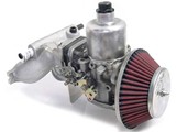
General Guidelines for Installation of HIF-6 or HIF-44 Carburetors
These guidelines make several assumptions, among which are:
1) You own a workshop manual covering the SU HIF-series carburetors. A number of good-quality manuals dedicated to the SU are available and are highly recommended. It is strongly recommended that you understand the theory of operation and the mechanical layout of the carburetor before you start.
2) You have installed the intake manifold and carburetor with all correct gaskets and fittings and have obtained throttle and choke cable of sufficient length to correctly operate the carburetor.
3) You have installed at least two throttle-return springs.
General
The HIF-series carburetor differs from the HS-series primarily in: 1) The design and location of the float chamber, which has been incorporated in the body of the carburetor, and 2) The introduction of temperature-sensitive mixture control (a bi-metallic strip fitted to the jet adjusting screw mechanism) to compensate for varying fuel densities resulting from changes in fuel temperature. These procedures cover very generally the connection of both the throttle and choke linkages and provide a key to correctly dealing with the various tubes and ports of the carb.
Choke and Throttle Cable Setup
Route the cables as required for your particular installation and connect them to the linkage attachment points. Adjust both cables to give full range of motion without binding. The gas pedal should open the throttle fully at the same time it hits the floor. If the pedal travel is stopped by the throttle reaching the full open position, the result will be stretched and/or broken cables, bent linkage parts and increases the possibility of a jammed or sticking throttle.
Make sure that the linkage is free of any bind or interference and that it the return springs close it completely when released.
The choke cable requires the same care. Adjust the cable such that it gives the full range of motion with no binding, taking particular care to see that it completely disengages when the choke cable is pushed to the fully off position.
Carburetor Hoses and Ports.
Note that all locations are described based on holding the carb in your hand with the suction chamber upright and the rear of the intake throat (butterfly end) facing away from you.
1) Vacuum connection. Located at the rear of the suction chamber, it is a tube about 1/8” in diameter and has a prominent nipple on the end. If you are not using a vacuum-advance distributor, cover this tube with some sort of blank tube cover or line cap. If you plug the tube (or any other tube or hose connection for that matter), make sure you can unplug it should you require its use in future.
2) Float bowl vent. This is a tube about 1/4” in diameter located on the right side of the carb at the base of the suction chamber. Connect this to the air cleaner.
3) Fuel inlet. Located directly below the float bowl vent. Connect this to the supply line form the fuel pump. This line should have a hose clamp around it at the carburetor for safety reasons.
4) Large tube at right base of suction chamber and to the rear of the fuel bowl vent. Cap this line. You will not be using it.
Initial Settings and Adjustments.
Before starting the engine, ensure that the ignition system is in good condition and that point and timing settings are correct. Also check and ensure that the carburetor dashpot oil is at the correct level.
Remove the three securing screws and remove the suction chamber and piston. Looking straight down through the hole, set the jet needle tube at flush with the bridge and the back it down 1/2 turn. The mixture adjusting screw is in a tunnel on the right front, directly below the fuel inlet tube.
Refer to your manual(s) for further tuning procedures once the engine is running.
| SU Type | Camshaft | Std Air Filter | K&N Air Filter |
|---|---|---|---|
| 1.5" HIF | MD256 | AAK | AAU |
| MD266/276 | AAA | AAM | |
| MD286 | ABY | ABY | |
| 1.75" HIF | MD256 | BDL (BAK) | BDK |
| MD266 | BDK | BCE | |
| MD276/286 | BBC | BBC | |
| MD296 | BBC | Will need modifying by hand | |
| 1.5"X2 | MD256/266 | AAV | |
| MD276 | AAA | ||
| MD286/296 | AAM or ABY (Richer) |

