

Gear Box Rebuild
Gearboxes may seem complicated but they are very simple in their construction, and surprisingly easy to put together. The main issues are having the right tools to do the job. So here's a list of what you will need. SEE VIDEO HERE
- Torque Wrench with a maximum range in excess of 150lbft
- 1 1/2" deep socket ( a ball joint socket is ideal )
- Small ratchet and a long extension is useful
- Other sockets 1 1/8, 9/16, 1/2, 7/16, 3/8
- Small cold chisel
- Steel punch (1/8" diameter)
- Larger steel drift
- Mallet (soft and hard headed)
- Small screw driver
There are three main rotational parts in the gearbox, the 1st motion shaft ( or input shaft ) which carries the bottom drop gear and what could be called 4th gear, the laygear which transfers the power from the input to the rest of the gearset, and finally the 3rd motion shaft which carries all the remaining gears.
First of all make sure you have everything you need.. 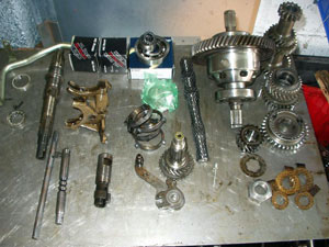
The first part which should be assembled is the 3rd motion. The shaft should be checked for signs of wear and replaced if necessary, new ones are not cheap, so sourcing a good second hand one is the preferred method. 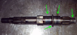
Place onto the nose end ( the one without the thread ), the needle bearing for the 3rd gear and then into the hole in the shaft adjacent to this the spring and plunger for the gear retainer ring..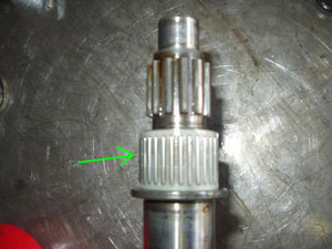
The third gear can now be slipped over the plunger and onto the bearing. Notice the presence of the oil can, everything should be well oiled as it is put together.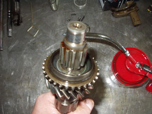
And the plunger.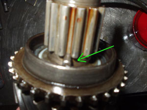
The retainer ring is then placed over the splines with the deep grove next to the plunger.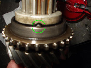
Using a small screwdriver or punch, the plunger can be pushed in and the retainer pushed into place, and then turned to lock. You will hear a click as the spring pushed the plunger into the retainer.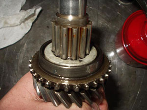
That's now 3rd gear installed, now turn the shaft around and perform much the same operation for 2nd gear. This time the retainer spring has two plungers and a hole which goes all the way through the shaft.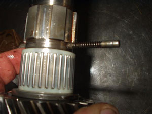
Push this through and position the 2nd gear onto the shaft. And then the retainer.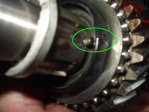
You will notice 2 small holes in the 2nd gear, which line up with the plungers, these are to help push the plungers in so the retainer can be locked in place. First push the retainer down having push one of the plungers into the shaft, there will be enough give in the retainer for you to hold it in by pressing down on the retainer.. From the other side press the plunger in through the hole in the gear using a small screw driver (or in my case a small brass rod)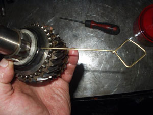
The retainer can then be pushed in and turned; you will hear two clicks this time as the plungers lock the retainer.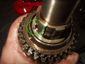
If you ask me that's the hardest bit of a rebuild completed, 2nd and 3rd gears are now locked onto the 3rd motion shaft.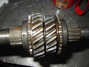
Next will be the 1st/2nd Synchromesh, but the all important baulk ring must not be forgotten, which is just dropped onto the 2nd gear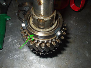
And then the synchro itself is place on to ( notice the cog on the outside is towards the 2nd gear, get it the wrong way round an you will not be able to select gears )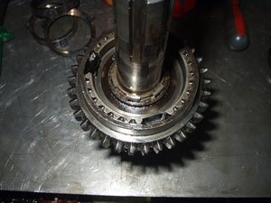
The 1st gear is next in line, but before that the bearing race ( or top hat ) must be placed on the shaft, this helps retain the synchro and something for the 1st gear to run against.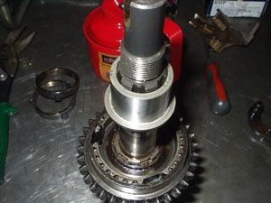
This is quite a tight fit and may need to be drifted in ( especially if a new on is being installed as it is here ), but I find buy placing the 1st gear bearing and gear on the top hat it can be pushed into place by hand. Don't forget the baulk ring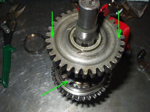
That completed, and the 3rd/4th gear synchro placed on the other end ( notice the positioning of the rib round the outside of the synchro again ) with the baulk ring, then the 3rd motion shaft is ready to be put into the case, but put it aside for one moment.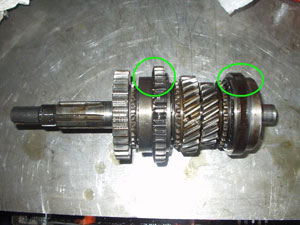
The case should be clean and free of any loose particles, you'll notice that this one is not shiny clean as would a customer one be, but this is one which after 2 days in dip would still not clean up. The outside however, is sparkly clean!!
The first item to be installed in the case is the Selector shaft and interlock spool which are inserted from within the case and should be turned away from their normal position, this will leave room for the selector levers to be installed.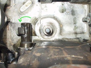
The selector levers are placed on the pin which is besides the selector, first will be the pivot bush (like a sleeve), and then the reverse lever, a thin spacer washer, the 3rd/4th lever, which has a chamfer cut on both sides of the lever, another thin spacer, and then the 1st/2nd lever, which only has a chamfer on the upper side. It is all then retained by a washer and a nyloc nut (Always use a new nut, never reuse nyloc nuts). It's also worth while checking that the selector can function with the levers.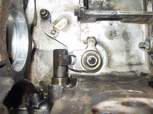
The Selector fork can not be installed, but placing the 3rd/4th fork in the case followed by the 1st/2nd so that the line up with the selector levers. The selector shaft can then be pushed through from the hole in the case and through the forks, making sure the hole in the shaft for the split pin lines up with the hole in the 3rd/4th fork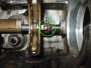
And when in place the pin can be punched in. At this time the reverse idler should be installed and the oil strainer if a CPU is not being fitted.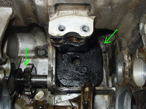
With all that now in place, the 3rd motion shaft can be introduced into the case. This is done by holding it on one hand and lowering the pinion end of the shaft in and through the main bearing retainer.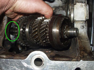
The shaft can then be lowered down into position with the synchro sitting in the selector forks. You will notice that there is a small recess in the casting which allows the nose to be lowered through with ease. Notice the absence of the strainer as this box will have a CPU, central oil pickup.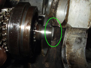
The 3rd motion shaft is now ready for the the main double roller bearing to be installed. This is the workhorse of the box and ideally should be renewed. The new bearing is supplied without the locating ring; this must be removed from the old bearing.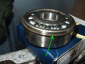
This is then placed over the 3rd motion shaft and drifted into the case..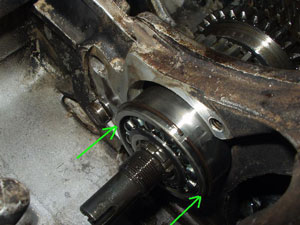
At this point keep an eye on the synchros; what you don't want to happen is the shaft to move so much that they are pulled apart by the selectors (balls and springs everywhere).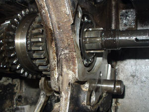
Now it is time to concentrate on the other end of the gearbox, and installing the 1st motion shaft and single roller bearing. I have found it easiest to place the bearing on the shaft first and then to drift it into the case. Notice the baulk ring in place too.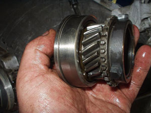
And then into the case, remembering to put the nose roller bearing on the nose of the 3rd motion shaft.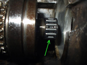
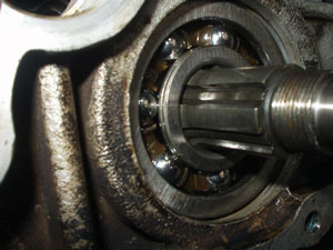
And then the circlip to hold the bearing in place.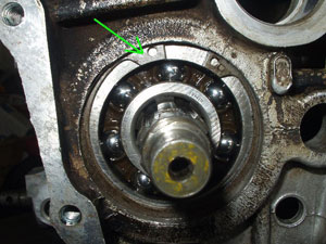
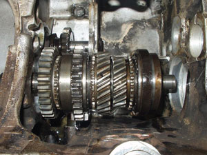
This now shows two of the three rotational gearbox parts in situe. Don't be worried is some of the gears (especially 3rd will not spin) this is due to the fact that the gearbox has not been torque'd up which will pull the 1st and 3rd motion shafts apart a little and free up the gears.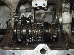
Now is the time to place the CPU into the gearbox if being fitted, but only in a vague position as it will have to be installed hand in hand with the laygear.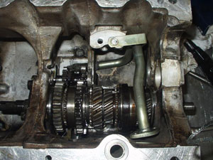
Before the laygear is added it is important to put a standard (or measured) set of thrusts into the box which will become apparent later.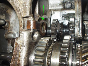
And with one competition Layshaft (this is an A series single step type, A+ have two steps and only 2 bearings) and bearings to install.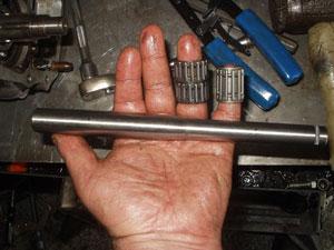
The bearings are placed into the laygear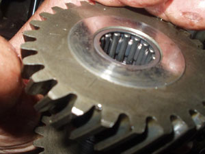
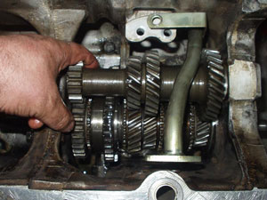
And then the laygear is placed into the gearbox, with the CPU and the thrusts this can be a bit of a fiddle but will get in eventually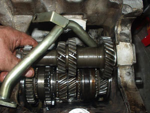
Now the importance of the endfloat and thrust washers… The gap between the end of the laygear and the thrust must be measured using a feeler gauge.
Now the importance of the endfloat and thrust washers… The gap between the end of the laygear and the thrust must be measured using a feeler gauge.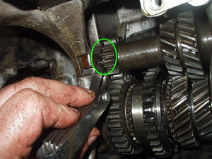
Which this time turned out to be 6 thou (0.006 of an inch), this is right at the limit of the tolerance for end float (should be between 2 and 6 thou) so the Layshaft has to be removed and the small thrust washer replaced for a slightly thicker one, there are a number of different thicknesses available, and as you may remember I said start with a standard one (which is the thinnest), using a micrometer I measured a few of the others I had and found one which was suitable.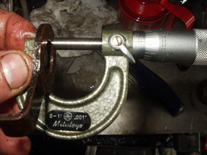
And after a quick swap over, the endfloat was down to 3 thou, which is much more acceptable.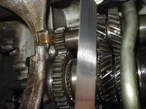
With the laygear installed you can now think about completing the installation of the gearset and pinion, the first thing to be added is the 3rd motion bearing retainer. This should be attached using the bolts to a â€oejust nip†tightness, and with most things within the mini gearbox will need the clearance checking.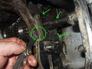
In this instance I could just squeeze a 2 thou feeler in, anything less than 5 thou is ok, any more and shims should be added. Not only does the 3rd motion retain hold the bearing, it also retains the locking plate for the reverse idler shaft and the lay shaft, each of which have a slot in so they can be rotated using a screwdriver to help locate the locking plate, and the retainer can be bolted in place with it's lock tabs bent over.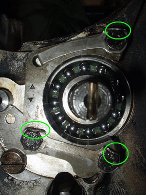
This is an A+ case so only 3 bolts are used, A series cases have 4 bolts but this introduces a weak spot in the web, which can crack, as shown ( this was my gearbox case which is why this pictorial rebuild is taking place )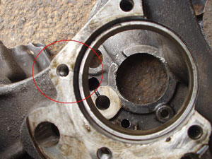
With the retainer installed and torque'd up, then the diff pinion can be placed on with a locking washer and big retaining bolt, and at the other end the desired style of input gear and locktab washer and bolt.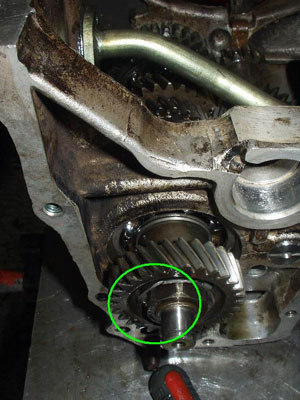
And the oil feed (CPU or standard) can be secured.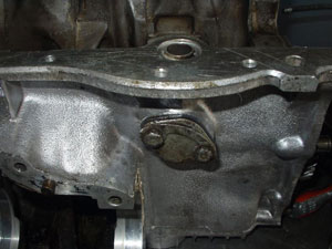
Before the gearbox can be finally torque'd. The only way I have found to do this simply and quickly is; first disengage the selector and select first and forth by tapping (hitting) the synchros to engage, and then turn the box upside down on the floor, stand on it and pull the torque wrench up, this needs to be capable of dealing with 150 lb ft torque, and must be done on both the input and output ends.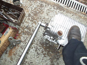
hey-presto one gearbox with all gear spinning freely, if they do not then something is wrong! ( make sure you have de-selected 1st and 4th and re engaged the selector )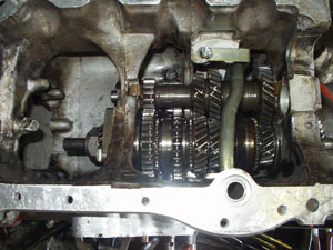
All that's left to do now is install the speedo take off, and the differential. Turn the box on its front so the diff case is facing upwards, and place the whole differential onto the gearbox, as far to the right as it will go ( this will help with setting the preload on the diff bearings later )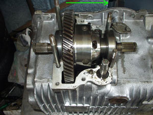
Don't get too confused if your differential does not look like this, this particular item is a Tran-x X Pin diff and much stronger than the original cast caged single pin diff, but the installation is exactly the same. With the diff in place, the rest of the diff casing can be fitted, and the right hand end plate. These should be fitted with the gaskets, and as you torque up the end plate this will push the differential assembly towards the left.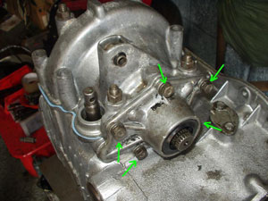
Now, at the other end of the diff casing, install the other end plate Without the gasket and tighten the bolts to the just bite point again, and again using feeler gauges measure the gap.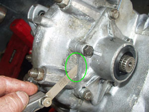
Here it is 5 thou, what you need to do is take that away from the compressed width of a gasket, 7 thou, which leaves 2 thou end float. The preload on the bearings is equivalent to 4 thou, so you need to add the end float to the preload, which gives 6 thou, and the thickness of the shim required. What I do now is disassemble the diff casing, and oil soak all the gaskets and rebuild. This helps with the seal of the gearbox.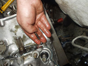
Not forgetting to put in the selector shaft locating sleeve, ball bearing and spring And the selected shims for the preload
One completed differential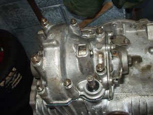
And a new idler bearing in the side of the case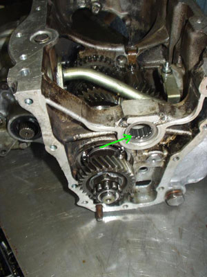
And speedo housing on the other end.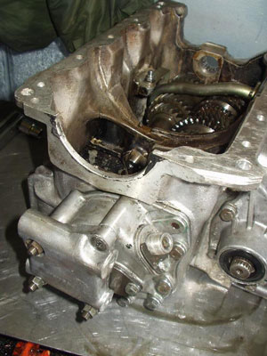
And that pretty much the end of the story.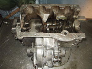
Related Articles:


