Mini Automatic to Manual Conversion Basic Information (Revised Feb 24, 2010)
The following is an overview of the steps to convert a Mini from an automatic transmission to one with a manual transmission/gearbox. It is not a step by step description of all the possible combinations you may run into, but it gives a good overview. It also applies specifically to the English built cars. There may be minor variations for cars built/assembled outside of England.
Assumptions Made and Areas Not Discussed In Detail.
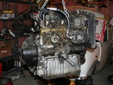
1. Assume the entire power unit from a manual gearbox car is to be swapped into the engine compartment of a Mini originally equipped with an automatic transmission.
The engine blocks of an automatic Mini and a manual gearbox Mini are not interchangeable. An automatic block can be modified to fit a manual gearbox, but it is skilled work and beyond the scope of this write up.
2. Assume the power units being swapped are both of the same capacity; e.g. both are 1275cc units.
There are some differences between small bore and large power units that have to be dealt with in any engine swap, regardless of the transmission type; e.g., upper radiator hoses and brackets are not the same for 998s and 1275s.
3. Assume the power units are from the same generation.
Early automatics used Hardy Spicer U-joints and later ones used inner CV (“Pot”) joints. Mixing would require axle changes. There is also the issue of installing rod change gearbox shift linkage into a pre-rod change body and visa versa. (See MMKT0803, for instance.) And there are issues between A and A+ engines regarding starters, generators/alternators, and distributors. There may even be issue with exhaust system type and clearance to deal with. All of these issues can be solved, but the job is much less complicated if the cars are of the same vintage -- or you have access to as much of the donor car as possible.
Changes To Make
1. Subframe and Motor Mounts
The automatic front subframe is slightly wider to accommodate the automatic transmission, and the front (radiator end) and rear (clutch end) motor mounts are different. A manual subframe could be installed directly into the automatic car as long as it is of the same type (single bolt or two bolt). This would be a much bigger job than using spacers, as discussed below.
To install a manual gearbox power unit, the following are necessary.
· Obtain two manual gearbox motor mounts. (21A1902)
· Make two spacers that will be used between the front and rear motor mounts and their mounting points on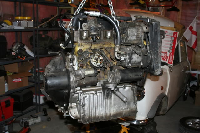 the replacement power unit. This widens the mounting base of the manual gearbox power unit to fit into the wider automatic subframe. The spacers should be 9 – 10mm or 3/8” thick with three holes for the mounting bolts to pass through. New, longer mounting bolts will be needed. The front three (radiator end) are fine thread (5/16” 24) and the rear three (clutch end) are coarse (5/16” 18). The front (radiator end) manual motor mount has narrower spaced subframe mounting holes than the automatic mount it replaces. Use the new mount as a template. Line up the rear hole and use the motor mount’s front hole location to drill a new hole in the subframe to match the new mount.
· Reuse the automatic upper stabilizer bar (21A1817). It is slightly longer and will keep the new power unit at the right tilt. Now would be a good time to replace the rubber bushings (CRC5329), if they are worn, or to upgrade to any of the poly bushings available (WB4, for example). Also, consider adding additional engine steadies; especially, if the new gearbox is a rod change type and/or if you have modified the new engine to get more power. (See MSSK and MSSK1, for examples.)
2. Clutch Hydraulics
· Obtain a clutch master cylinder. (GMC1008 or GMC1008/ORIG), a clevis pin (CLZ512), and a cotter pin or hitch/R pin to secure the clevis pin. If you’re reusing old parts, make sure the clevis pin is not worn. Replace it if it shows any signs of wear. You’ll most likely need one or more gaskets, as well. (See 31G279, 31G840, and NAM9197.)
· Obtain a clutch slave cylinder and hose appropriate for the manual gearbox power unit. If an A+, you might need the mounting platform for the clutch slave if it doesn’t come with the power unit. (Slaves: 22A233, GSY118; Hoses: 13H300 (braided version C-AJJ4025) and GVP1009; Verto mounting plate, DAM5992.) Also look at spring (1G5999), spring anchors (2A3600 and 2A3601), if applicable, and check the clutch arm, rod, and both clevis pins for wear. For related articles, see https://www.minimania.com/web/SCatagory/CLUTCH/DisplayType/Technical%20Information/DisplayID/1086/ArticleV.cfm and https://www.minimania.com/web/SCatagory/CLUTCH/DisplayType/Technical%20Information/DisplayID/153/ArticleV.cfm
· A clutch pipe will need to be obtained/fabricated to go from the clutch master cylinder to the mounting point for the clutch slave cylinder hose on the firewall. (See SPA12, SPA32.)
· A clutch pedal will need to be installed on the pedal box, or a pedal box from a manual gearbox car can be swapped in. It’s a good idea, if using used parts, to obtain them from a car of the same vintage to make sure pedal angles and foot pad sizes match your car. (See https://www.minimania.com/web/CatPage/3-9/Chapter/3/Page/9/Mini_Cooper_Catalog.cfm)
3. Shift Mechanism, Drive Shafts, CV and U-joints
· If not supplied with the manual gearbox power unit, all the shift linkage, the lever, the boot, and the boot retainer applicable to the gearbox must be obtained.
· There are many combinations of shift mechanisms and body floors, but the most common now is likely to  be that the Mini from which the automatic is being removed has the square section body tunnel associated with rod change cars and the automatic uses inboard CV/pot joints. (Pre-rod change cars had a round section body tunnel and early automatics used Hardy Spicer U-joints at the differential end of the drive shaft. Note, too, that the axles for Hardy Spicer and inboard CV/pot joints differ.) Also, it is likely that the donor car’s power unit is a rod change with inboard CV joints. If you get all the parts from the donor car you’re home free. Note: if both cars use pot joints (inboard CVs) and you remove the engines by removing the pot joint boots and pulling the inners out with the axles, do not mix inners from one car with outers from the other. Two different sizes were made and you can get a mismatch. Use the entire pot joint from either car unless you are sure you have a good match.
4. Starter Inhibitor Switch
· Automatics had a starter inhibitor switch that would not let the engine start when the car was in gear. The switch will not be used with the manual gearbox so the wires involved need to be located and joined together; otherwise, the starting circuit will not allow the car to be started. There were at least three different versions used for this switch depending upon the age of the car. Refer to your workshop manual.
5. Speedometer and Final Drive
· With the many different final drive ratios and speedometers used in Minis over the years, it is unlikely that the manual gearbox power unit will drive the speedometer in the former automatic car correctly. If the speedometer from the donor car is available and it is of the same type as in the automatic car, use it. If not, the easiest solution would be to have the speedometer recalibrated. Note, too, that different speedometer cables are required for different types of speedometers. Use the cable that was in the automatic car and make sure you connect it to the gearbox before the new engine is installed.