
Found 35 Messages

|
Total posts: 946
Last post: Dec 26, 2023 Member since:Aug 6, 2011
|
Cars in Garage: 0
Photos: 0 WorkBench Posts: 0 |
|
well, this project seems to be finished. Thanks to all for your help and replies to this issue.
Yesterday, Doug helped me to properly install the poly bushings and now the car handles a lot smoother and softer.
cheers,
Abel
|
|
Total posts: 8382
Last post: Jan 13, 2022 Member since:Feb 7, 2006
|
Cars in Garage: 0
Photos: 0 WorkBench Posts: 0 |
|
thanks Dan, I will try that when I go under the car to get the poly bushing for the tower bolt.
Excuse me my ingnorance, but what is exactly a "kack pad"?
thanks,
Abel
I think Dan meant to say jack pad (they are small squarish pads on the front and rear corners of the floors) close to the sills.
If in doubt, flat out. Colin Mc Rae MBE 1968-2007.
Give a car more power and it goes faster on the straights,
make a car lighter and it's faster everywhere. Colin Chapman.
|
|
Total posts: 946
Last post: Dec 26, 2023 Member since:Aug 6, 2011
|
Cars in Garage: 0
Photos: 0 WorkBench Posts: 0 |
|
thanks Dan, I will try that when I go under the car to get the poly bushing for the tower bolt.
Excuse me my ingnorance, but what is exactly a "kack pad"?
thanks,
Abel
|
|
Total posts: 9542
Last post: Apr 18, 2024 Member since:Aug 14, 2002
|
Cars in Garage: 0
Photos: 0 WorkBench Posts: 0 |
|
You can jack the car on or near the front corners of the front subframe enough to get the weight off those points. The back of the subframe should sag down enough especially if you loosen the tower bolts. You may have to undo the engine steady brace(s) to the firewall as well.
Or you can put a block of wood under the floor directly below the firewall panel - the vertical panel will distibute the load and not bend the floor pan. That tiny clip that looks like a kack pad is NOT! It is only a clip for the body assembly jig when it was built.
Or if your car has the sill jack pockets at the floor crossmember and it is in solid condition, you could jack one side of the car from there.
While you have the carpet and subframe mounts out, check the floor for metal fatigue cracks at those mount locations. I had a creak/snap sound in my car when going on/off the throttle, which turned out to be such a crack. The cause was a broken engine steady bracket at the firewall, which allowed the engine to apply too much front-back rocking torque on the subframe, resulting in metal fatigue.
.
"Hang on a minute lads....I've got a great idea."
|
|
Total posts: 946
Last post: Dec 26, 2023 Member since:Aug 6, 2011
|
Cars in Garage: 0
Photos: 0 WorkBench Posts: 0 |
|
The plan was to use alloy tear drops at the front, Plastic at the tower tops and std rubber at the base of toe board. I did not make that clear which could happen when you install them often and try and tell someone else how they go. I noticed it right away but sent an e mail rather than point it out here. Steve (CTR)
thanks Steve. The email you sent me earlier makes more sense now.
While I am under the car, I wanted to replace this aswell //www.minimania.com/part/21A2599/Subframe-Mount-Rear-Of-Front-Subframe-Mk4-Mini--Cooper-On and wanted to ask what's the best way to do it. Where should I jack the car?
thanks,
Abel
|
|
Total posts: 4134
Last post: Oct 13, 2020 Member since:Oct 8, 2011
|
Cars in Garage: 0
Photos: 0 WorkBench Posts: 0 |
|
The plan was to use alloy tear drops at the front, Plastic at the tower tops and std rubber at the base of toe board. I did not make that clear which could happen when you install them often and try and tell someone else how they go. I noticed it right away but sent an e mail rather than point it out here. Steve (CTR)
|
|
Total posts: 7075
Last post: Nov 5, 2019 Member since:Apr 25, 2000
|
Cars in Garage: 0
Photos: 0 WorkBench Posts: 0 |
|
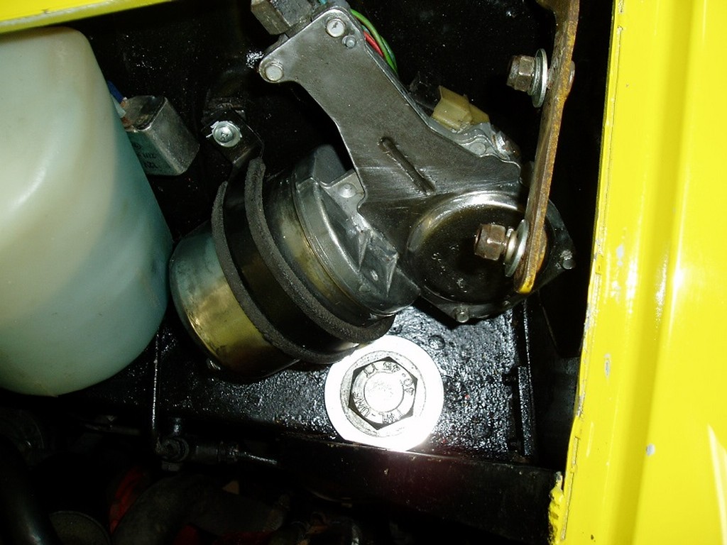
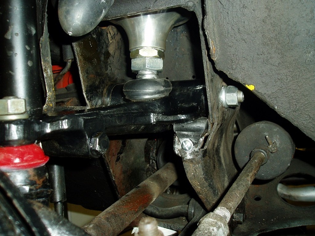
Well, in my opinion, if between the subframe tower and the bulkhead crossmember there's an aluminum spacer, the vehicle already had a solid tower mount kit installed which many consider the ultimate upgrade for handling and longevity. The polyurethane bushes won't be as rigid, but possibly transmit fewer vibrations and ultimately less noisy.
I have solid mounts on the towers and the 'teardrops' at the front and like them.
 The peasants are revolting...
 ![]()
"Gone with the Wind" - a brief yet moving vignette concerning lactose intolerance
|
|
Total posts: 946
Last post: Dec 26, 2023 Member since:Aug 6, 2011
|
Cars in Garage: 0
Photos: 0 WorkBench Posts: 0 |
|
my car is a 1978, so I figure it is a later subframe.
As for the cluster of bushings, yes, I need to figure out the proper way to install them. This is an 'improvement kit', as described by the manufacturer
|
|
Total posts: 7075
Last post: Nov 5, 2019 Member since:Apr 25, 2000
|
Cars in Garage: 0
Photos: 0 WorkBench Posts: 0 |
|
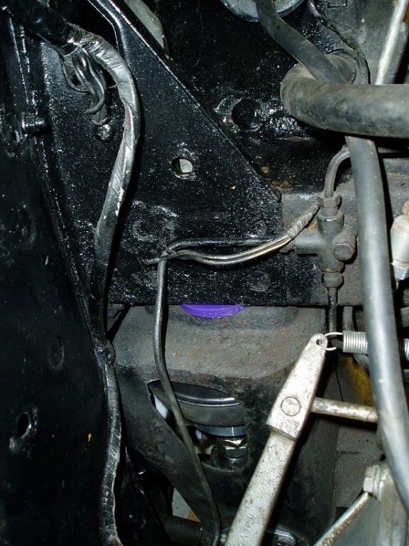
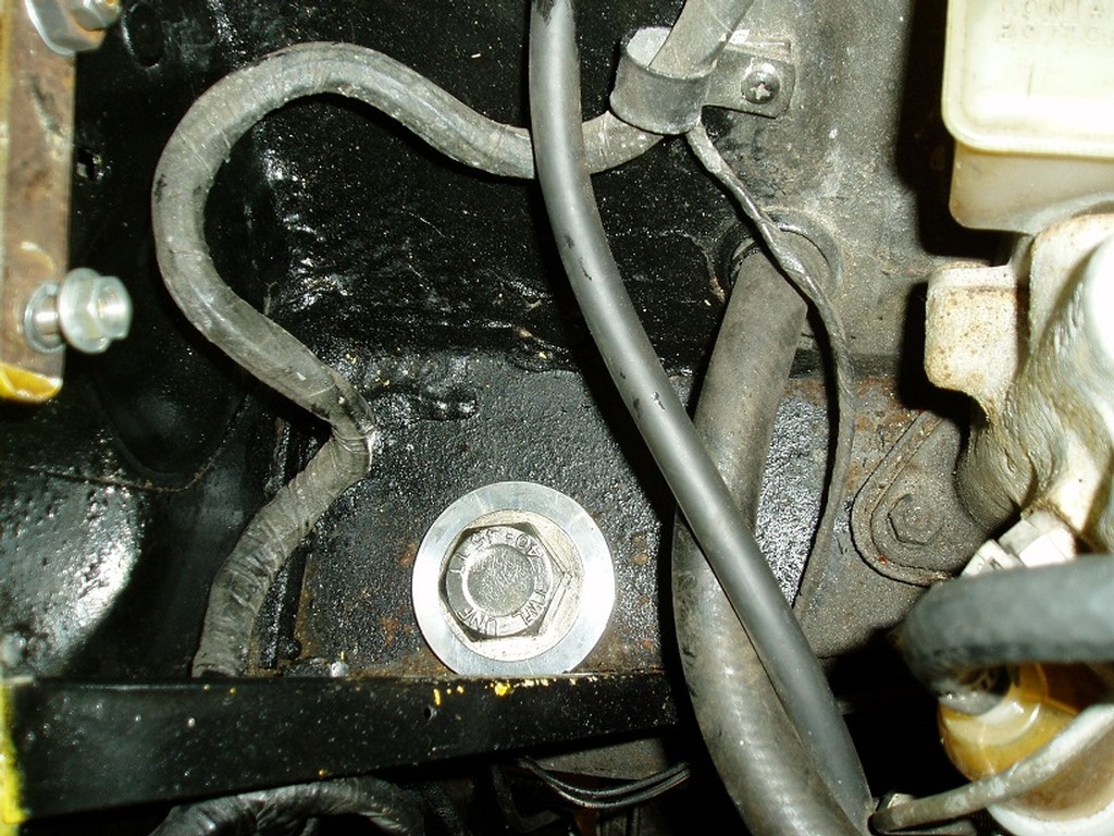
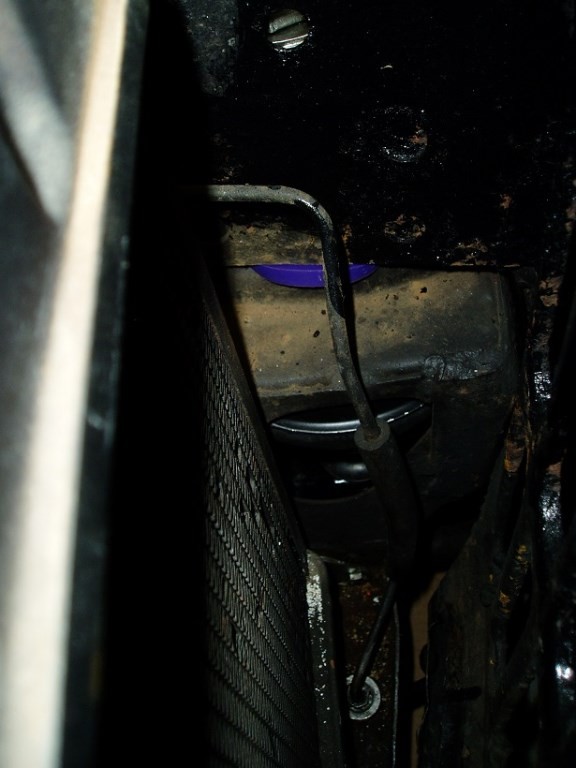
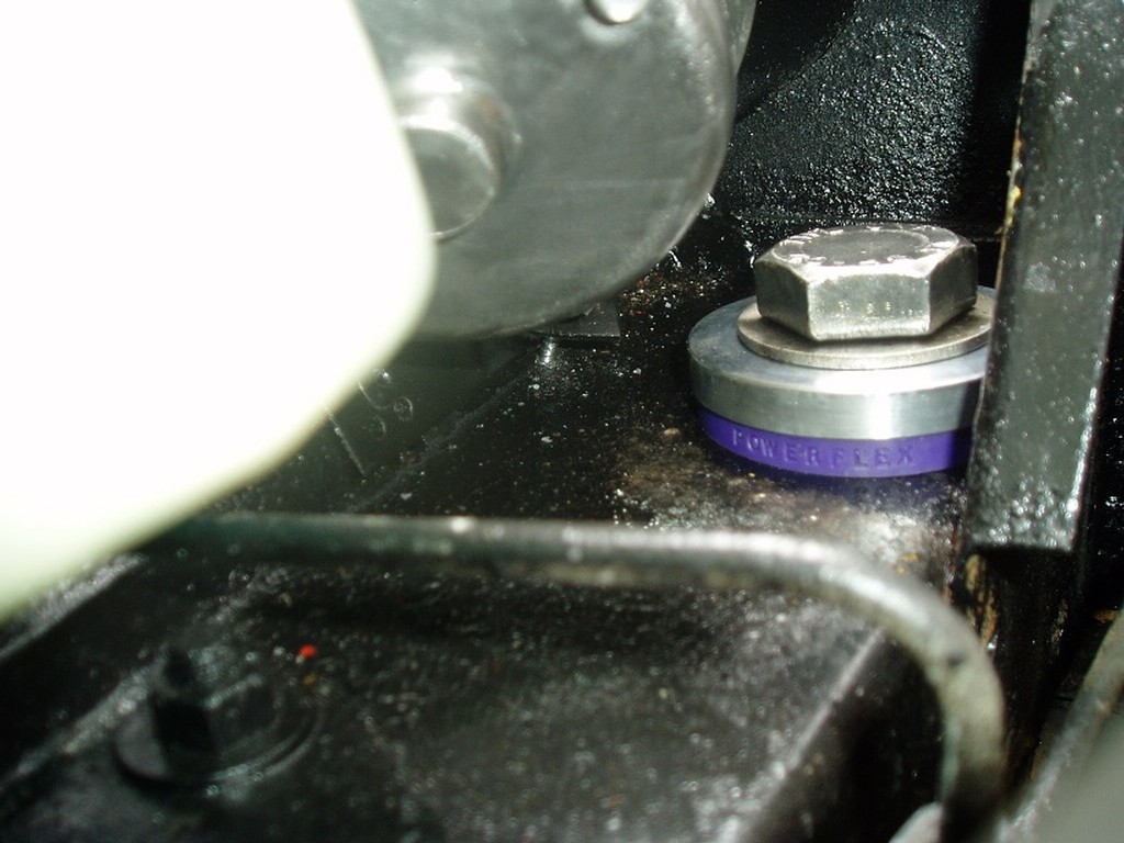
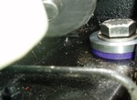
Absolutely, but the photo of the purple poly tower bush siting under the aluminum bush with the large bolt prompted me to assume that it's a later subby.
I don't know if it's just me, but it looks to me as though there's one too many bushes under the bolt head. Maybe the poly bushes come with a full-size thick washer that looks remarkably similar to the alloy top-bush? (Image from earlier post: Tower Bush)
The peasants are revolting... ![]()
"Gone with the Wind" - a brief yet moving vignette concerning lactose intolerance
|
|
Total posts: 13978
Last post: Jan 15, 2024 Member since:Jan 22, 2003
|
Cars in Garage: 4
Photos: 381 WorkBench Posts: 1 |
|
I image an earlier two bolt subframe will have a different toque value
"Everybody should own a MINI at some point, or you are incomplete as a human being" - James May
"WET COOPER", Partsguy1 (Terry Snell of Penticton BC ) - Could you send the money for the unpaid parts and court fees.
Ordered so by a Judge
|
|
Total posts: 7075
Last post: Nov 5, 2019 Member since:Apr 25, 2000
|
Cars in Garage: 0
Photos: 0 WorkBench Posts: 0 |
|
This might help:
From the Rover MPI Mini Workshop Manual RCL-0193ENG-2nd-Edition:
SUSPENSION
Wheel nuts:
Alloy wheels . . . . . . . . . . . . . . . . . . . . . . . . . . . . . . . 50 Nm
Steel wheels . . . . . . . . . . . . . . . . . . . . . . . . . . . . . . 60 Nm
Upper arm to front hub . . . . . . . . . . . . . . . . . . . . . . . 52 Nm
Lower arm to front hub . . . . . . . . . . . . . . . . . . . . . . . 52 Nm
Front hub to drive shaft - nut . . . . . . . . . . . . . . . . . . . 260 Nm
Front subframe turret bolts . . . . . . . . . . . . . . . . . . . . 67 Nm (49.41 lbs/ft)
Front damper to body bracket - nut . . . . . . . . . . . . . . 37 Nm
Front damper to upper arm - nut . . . . . . . . . . . . . . . . 48 Nm
Front subframe to body - nuts and bolts . . . . . . . . . . 25 Nm
Rear damper to body . . . . . . . . . . . . . . . . . . . . . . . . . 25 Nm
Rear damper to suspension arm . . . . . . . . . . . . . . . . 25 Nm
The peasants are revolting... ![]()
"Gone with the Wind" - a brief yet moving vignette concerning lactose intolerance
|
|
Total posts: 662
Last post: Apr 17, 2024 Member since:May 18, 2002
|
Cars in Garage: 0
Photos: 0 WorkBench Posts: 0 |
|
all the new and refurbished parts went back in without much trouble. Now I am trying to find the specific torque on the tower bolts. Anybody knows that?
Also, regarding the ride height, I installed hi-lows and wanted to ask what's the appropriate height for the front, measuring from the wheel arch to the center of the wheel,
thanks,
Abel
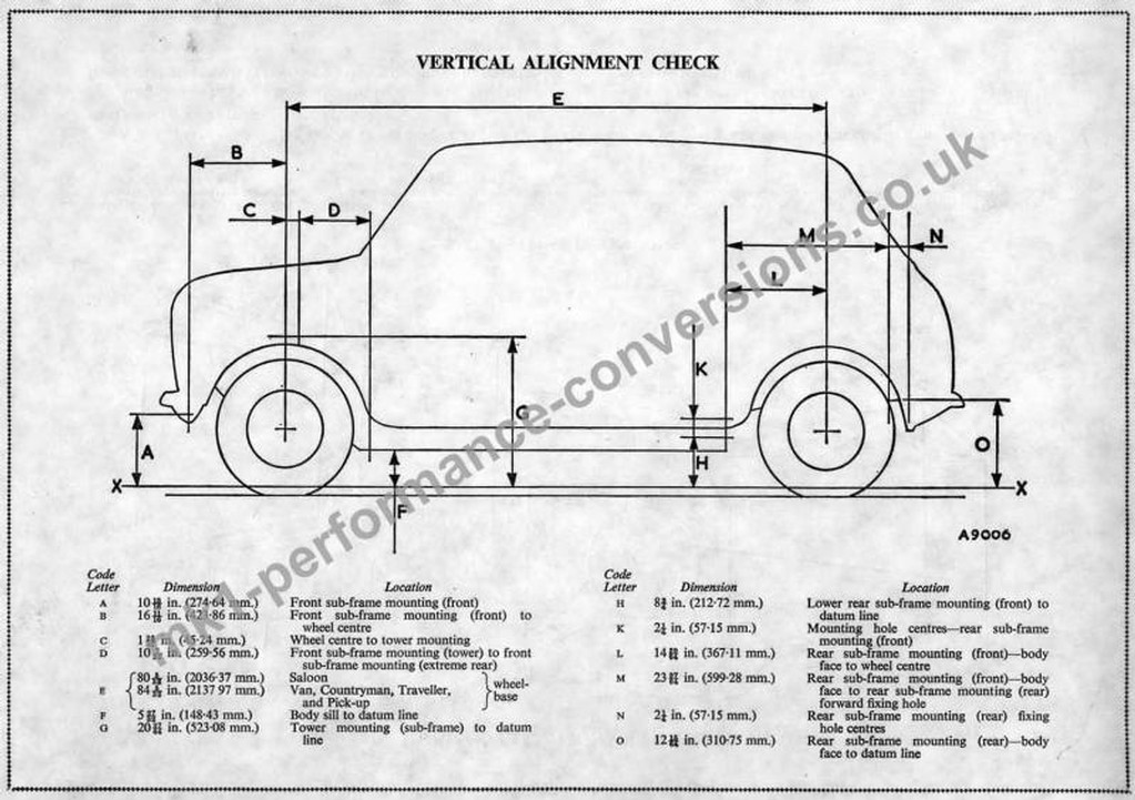
I've tried to get a good measurement from the various forums the best I could come up with is to set the Hi-Lo to the same length as the original trumpet.Standard alloy trumpet lengths front trumpet height as standard is 3.750" and the rear is 12.375" on the latest post 1979. The earlier ones were around 12.125". Dimensions from the knuckle end to the rubber cone seating face.
I also got this picture which may or may not help.
|
|
Total posts: 946
Last post: Dec 26, 2023 Member since:Aug 6, 2011
|
Cars in Garage: 0
Photos: 0 WorkBench Posts: 0 |
|
all the new and refurbished parts went back in without much trouble. Now I am trying to find the specific torque on the tower bolts. Anybody knows that?
Also, regarding the ride height, I installed hi-lows and wanted to ask what's the appropriate height for the front, measuring from the wheel arch to the center of the wheel,
thanks,
Abel
|
|
Total posts: 946
Last post: Dec 26, 2023 Member since:Aug 6, 2011
|
Cars in Garage: 0
Photos: 0 WorkBench Posts: 0 |
|
oh, yes, that and replace any rusty bolt and nut I found along the way
|
|
Total posts: 2022
Last post: Jan 14, 2022 Member since:Mar 8, 2002
|
Cars in Garage: 0
Photos: 1 WorkBench Posts: 1 |
|
make sure you grease the car frequently from now on! its the only way to prevent this kind of situation.
|
|
Total posts: 946
Last post: Dec 26, 2023 Member since:Aug 6, 2011
|
Cars in Garage: 0
Photos: 0 WorkBench Posts: 0 |
|
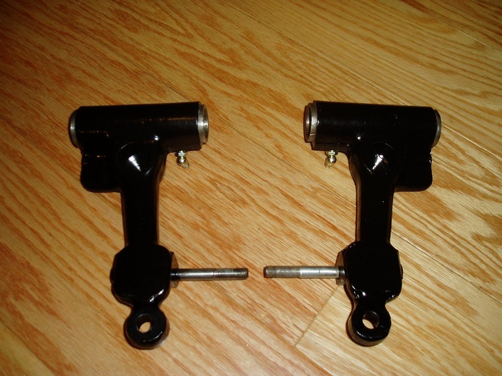
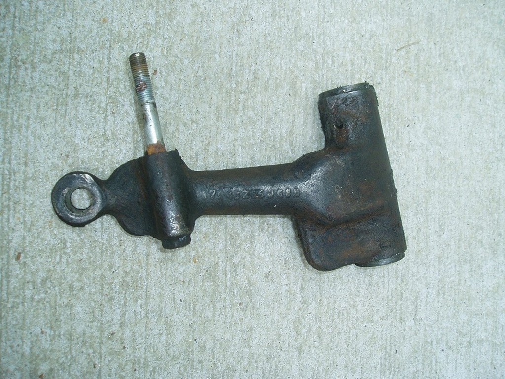
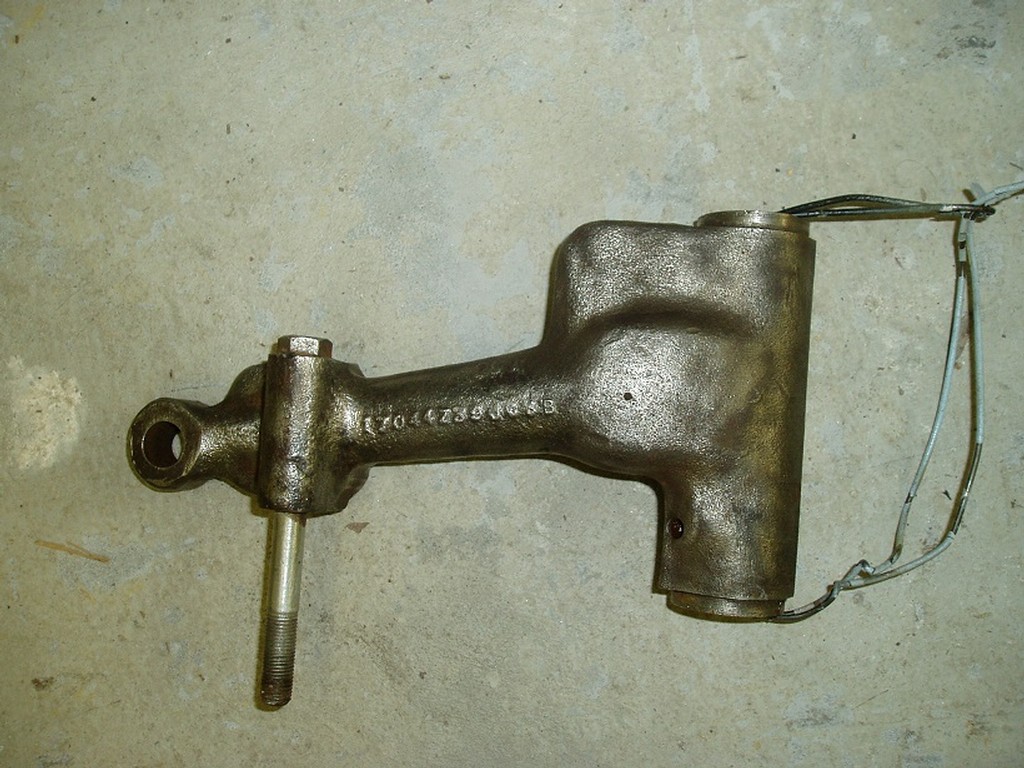
thanks to all for the replies and the help. As Doug mentioned, the left side did not present any problem at all. Now that I have the upper arms out, I'll give them some clean-up, paint and wait for new parts to arrive to put everything back together.
regards,
Abel
|
|
Total posts: 4134
Last post: Oct 13, 2020 Member since:Oct 8, 2011
|
Cars in Garage: 0
Photos: 0 WorkBench Posts: 0 |
|
I'd think he'd want to put a kit on one side. Steve (CTR)
|
|
Total posts: 2022
Last post: Jan 14, 2022 Member since:Mar 8, 2002
|
Cars in Garage: 0
Photos: 1 WorkBench Posts: 1 |
|
Once the penetrating oil had done its work and they got the arm in just the right position the pin levered right out.
+1 its the best way IMHO to remove it.. always worked nicely for me
|
|
Total posts: 9241
Last post: Aug 17, 2023 Member since:Jun 5, 2000
|
Cars in Garage: 0
Photos: 0 WorkBench Posts: 0 |
|
Abel and a neighbor tried again to remove the left top arm pivot pin. Once the penetrating oil had done its work and they got the arm in just the right position the pin levered right out.
I went over today to help him with the right side and it went perfectly. That pin had no rust and was well lubricated so the pin slipped out as easily as they did on my car a few years ago.
|
|
Total posts: 1723
Last post: Oct 20, 2020 Member since:Jun 18, 1999
|
Cars in Garage: 0
Photos: 0 WorkBench Posts: 0 |
|
I just joined the club and removed my upper a arm. Got it back together. For those that are about to do it , slide the rubber ring grease seal on the a arm (the side that faces front). Now onto the steering rack boots and alignment.
Found 35 Messages


