
| Orig. Posting Date | User Name | Edit Date |
| Feb 21, 2015 06:42AM | Dan Moffet | |
| Feb 20, 2015 04:44PM | jeg | |
| Feb 20, 2015 11:09AM | Dan Moffet | |
| Feb 17, 2015 04:16PM | jeg | Edited: Mar 5, 2015 05:12PM |
| Feb 8, 2015 05:23PM | jeg | |
| Jan 28, 2015 03:00AM | jeg | Edited: Jan 28, 2015 03:06AM |
| Jan 28, 2015 02:50AM | mur | |
| Jan 28, 2015 02:44AM | jeg | Edited: Jan 30, 2015 04:24AM |
| Jan 27, 2015 11:24PM | 1963SV2 | |
| Jan 27, 2015 10:32PM | mur | |
| Jan 27, 2015 06:44PM | 1963SV2 | |
| Jan 27, 2015 04:11PM | jeg | |
| Jan 26, 2015 08:33PM | jeg | Edited: Jan 27, 2015 04:05PM |
| Jan 26, 2015 08:23PM | mur | |
| Jan 26, 2015 07:34PM | jeg | Edited: Jan 26, 2015 08:07PM |
| Jan 26, 2015 04:13PM | jeg | Edited: Jan 26, 2015 04:28PM |
| Jan 25, 2015 03:30AM | jeg | Edited: Jan 26, 2015 03:34PM |
| Jan 24, 2015 08:18AM | mur | |
| Jan 23, 2015 11:08PM | jeg | |
| Jan 23, 2015 10:19PM | mur |

|
Total posts: 9542
Last post: Apr 18, 2024 Member since:Aug 14, 2002
|
Cars in Garage: 0
Photos: 0 WorkBench Posts: 0 |
|
John, I sometimes find that maturity is over-rated. (My wife says, often, that my 'age' is somewhere betwenn low teens and single digits.)
Shortly after I got my Mini, I took it to be sprayed, including body cavities, with a Waxoyl - like product. Even so, she (the Mini) gets tucked in for the winter the day they start applying slat to the roads here, and stays in the garage until snow is gone and we've had some good April rains to wash away salt. They load it on so heavily here that some days, when the road dries off, the traffic kicks up a fine slat dust that looks like fog - visible in full daylight. Right now our cold spell (several weeks) precludes washing cars (unless one has a heated garage or is an undertaker) and most cars are beginning to look the same colour, sort of a matt, dusty beige that hides paint colour. Even some black or red cars look more like they are just under a different coloured light source.
But all that doesn't stop me from wanting to do power and handbrake slides and turns. I get a bit of relief in empty parking lots and roads in my daily driver, which has 'all season' (meaning except real winter) tires, which aren't much better than summer tires. Yeeeeee Haaaaawwwwww!
.
"Hang on a minute lads....I've got a great idea."
|
|
Total posts: 7075
Last post: Nov 5, 2019 Member since:Apr 25, 2000
|
Cars in Garage: 0
Photos: 0 WorkBench Posts: 0 |
|
Dan, despite my obvious immaturity, I'm the one that's over 50.
I used to have a blast in the snow when my mini was still on 10 inch Dunlop tires. That was during the first 2 years that I owned it. Since then, I seem to invest more time, money and energy into it and nearly never use it.
That might change this year though, especially if I don't find a job - might be forced to sell my daily driver and buy a bicycle to get around and take the mini job-hunting. With that being said, I obtained a 2nd-hand electric water kettle today which will allow me to heat up the 2 cans of Waxoil that have no doubt solidified and give the mini a right proper under-floor and cavity spray. Can't be too prepared...
 The peasants are revolting...
 ![]()
"Gone with the Wind" - a brief yet moving vignette concerning lactose intolerance
|
|
Total posts: 9542
Last post: Apr 18, 2024 Member since:Aug 14, 2002
|
Cars in Garage: 0
Photos: 0 WorkBench Posts: 0 |
|
Is the car age 50, or are you age 50 (just to be clear)?
A Mini in winter is FUN... summer tires just add to the enjoyment. I (in my youth) used to apporoach our driveway and about 80 feet away flick the steering and the handbrake so as to arrive in front of the driveway going sideways. Also did a mile or so on a snowmobile trail on a closed road over about 2 feet of snow. All on biased-ply summers.
.
"Hang on a minute lads....I've got a great idea."
|
|
Total posts: 7075
Last post: Nov 5, 2019 Member since:Apr 25, 2000
|
Cars in Garage: 0
Photos: 0 WorkBench Posts: 0 |
|
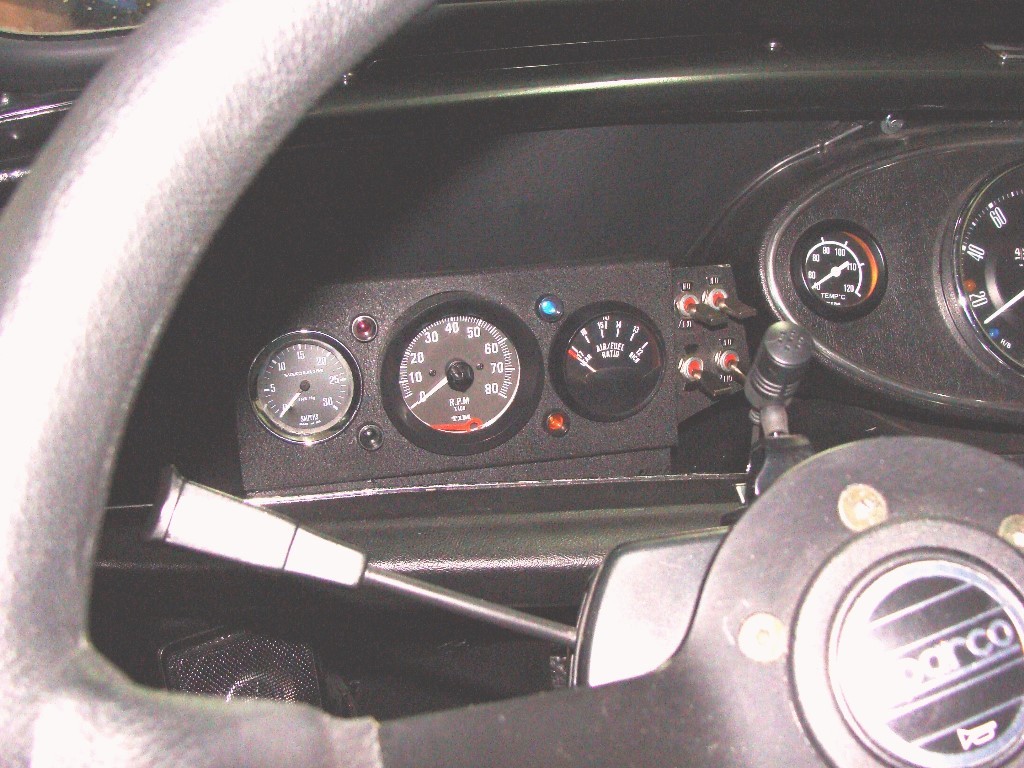
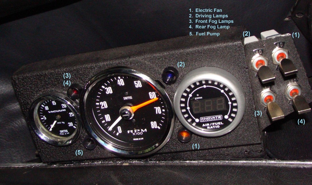
I finished it off today! No decent pictures, but definately a project worth the time. I'm delighted. Thanks to everyone who helped; I learned a lot in this project and made a few changes to the original concept along the way. Most notably, using separate dpst switches for the driving and fog lights. So, now that little box with 3 gauges has 5 switches and 4 indicator lamps. It wouldn't have been possible without the tutalage that I recieved.
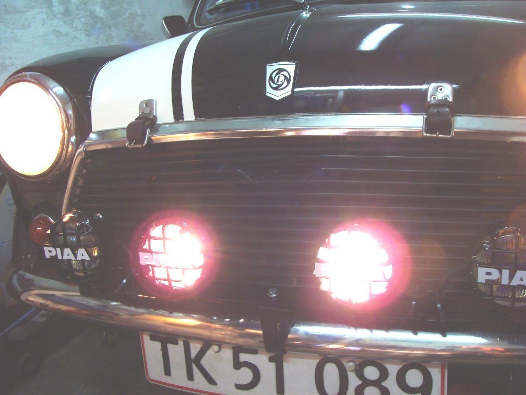
I made a 'calibrated aiming stick' and took the mini out and aimed them as best I could in a parking garage and I can't wait to try them out on a dark country road. The 'plasma ion yellow' fog lights are really 'yellow' and a flick of the switch illuminated the street in front of my apartment in a deep yellow glow. Very nice, almost soothing.
I drove somewhat enthusiastically back to the garage and 'forgot' that the cold, greasy road wouldn't be quite the same as with the summer tires. Well, there wasn't any traffic where the road turns sharply left; I gave a bit more throttle and the right rear came up as the left rear broke free. I slid a bit from the induced understeer and kissed the curb with the right rear. No damage, just a small skuff to the edge of steel wheel, but a reminder that rolling the car at age 50 might be embarrasing.
The peasants are revolting... ![]()
"Gone with the Wind" - a brief yet moving vignette concerning lactose intolerance
|
|
Total posts: 7075
Last post: Nov 5, 2019 Member since:Apr 25, 2000
|
Cars in Garage: 0
Photos: 0 WorkBench Posts: 0 |
|
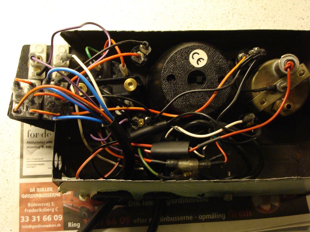
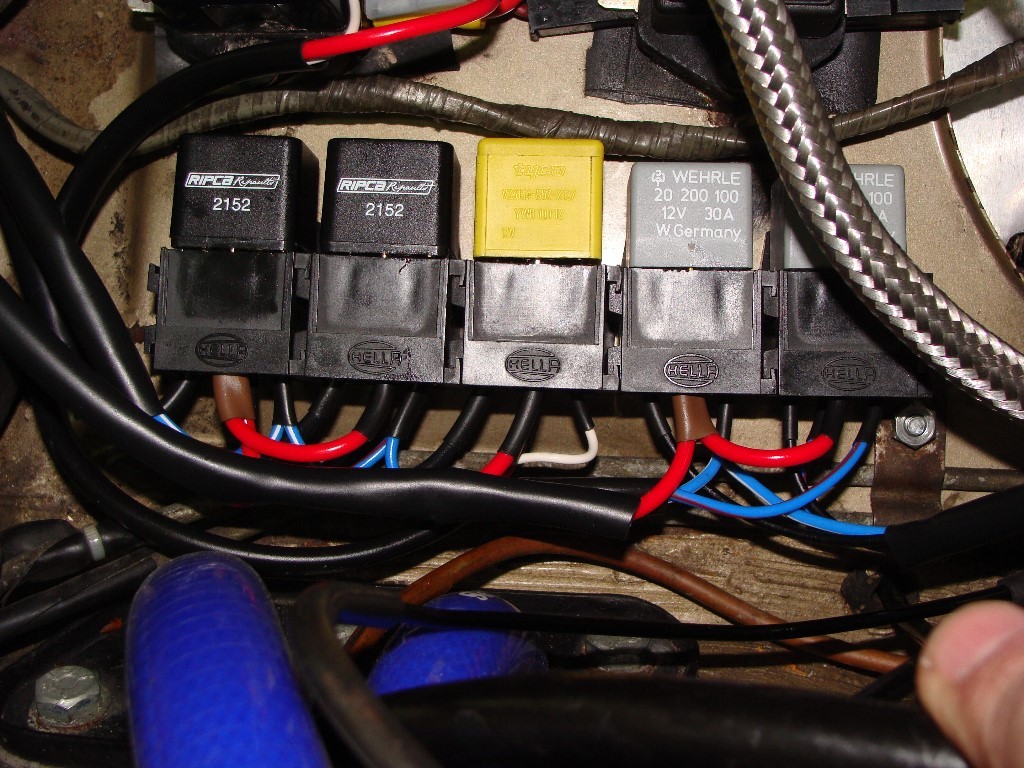
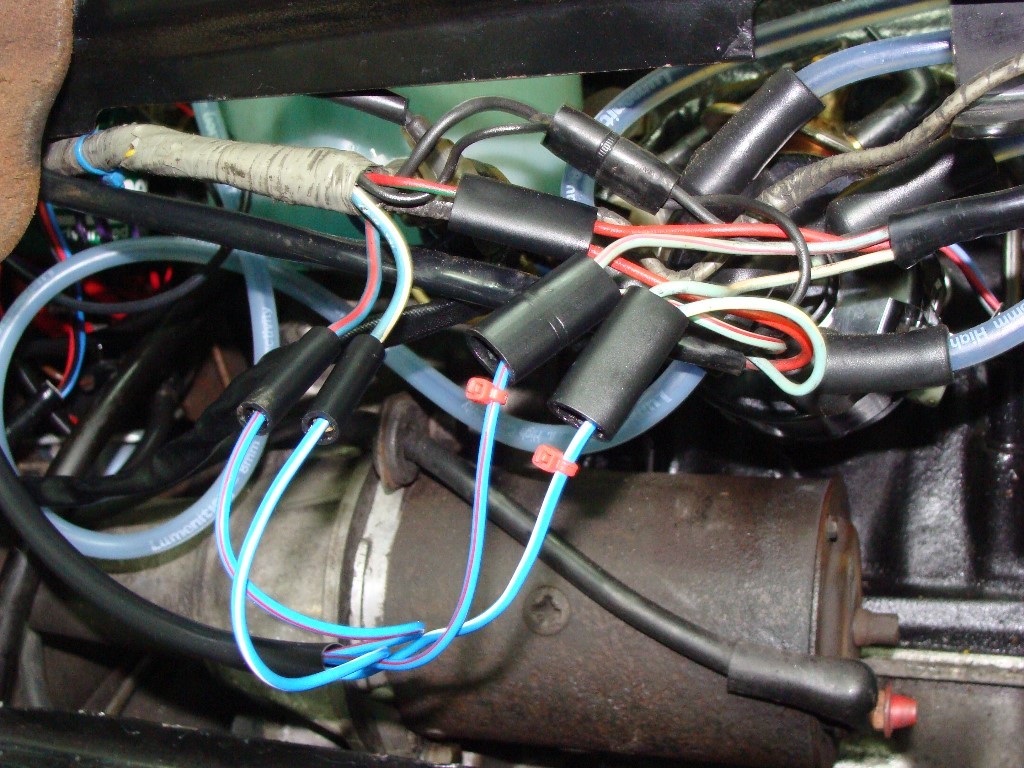
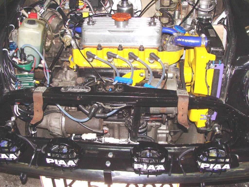
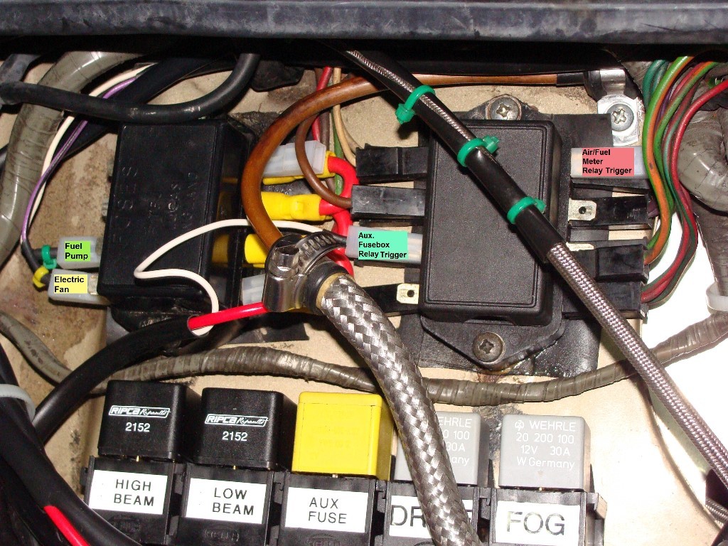
Right - If anyone was wondering, work on this is progressing nicely, though I haven't actually mounted any lamps yet.
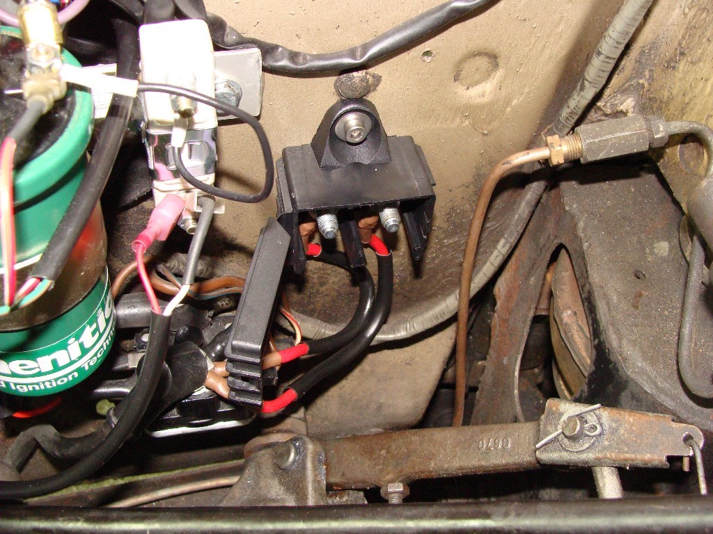
I've re-wired the gauge panel and switches, installed the junction box fro the (+) feed from the starter solenoid, redone the wires for the lambda sensor and electric fan, moved the horn relay, cut the side of the gauge panel and bent it forward to accomodate the new switch and have the row of 5 relays in place and wired. The 2 wires connecting the junction box have been replaced by a pre-made 22.5mm long red-colored 170A battery lead (of shocking poor quality) and there are 3 x inline fuse holders (40A ea. max capacity) to supply power to the headlight relays, 2nd fuse box relay and fog & driving lamp relays. I figured that even though I've got a row of 5 relays under the fuse boxes there will only be 3 functioning at a time (either high/driving lamp or low beam/fog lamp) and the 2nd fuse box, so the '+' is in two instances shared between 2 relays. I haven't installed in-line fuses between the 'trigger wires' and the relays; I have them, just forgot at the time.
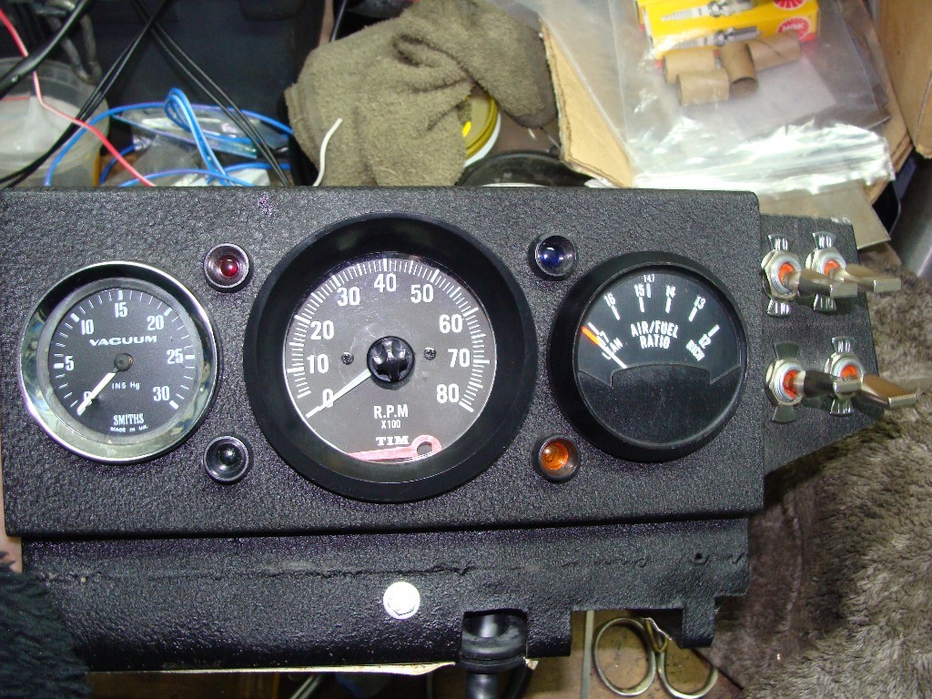
The attached images aren't the finished install, some wires have been changed and there's an incorrect ground lead on the backside of the gauge panel, but I forgot the camera at the garage when I took the unit home to show Hyacinth. In any event, they're close...
So now I expect a few painful hours under the dash to connect a bunch of wires to the connector blocks and finally install the fog & driving lamps. My new Innovation Motorsports MTX-L air-fuel meter will have to wait; the wiring bundle is 'bulky' and the sensor won't like the fuel additives I'm using, so I'm not sure what I'll do with it - maybe just use it with a tail-pipe adapter.
I broke my tach in the process, so if anyone has one... I'd like a black-faced Smiths, but could somehow never afford one...
The peasants are revolting... ![]()
"Gone with the Wind" - a brief yet moving vignette concerning lactose intolerance
|
|
Total posts: 7075
Last post: Nov 5, 2019 Member since:Apr 25, 2000
|
Cars in Garage: 0
Photos: 0 WorkBench Posts: 0 |
|
Oh yeah - I'll just extend the dashed line over to the text box where the dpdt connected to -
Edit: the image above is edited
The peasants are revolting... ![]()
"Gone with the Wind" - a brief yet moving vignette concerning lactose intolerance
|
|
Total posts: 5840
Last post: Nov 1, 2019 Member since:Nov 12, 1999
|
Cars in Garage: 0
Photos: 0 WorkBench Posts: 0 |
|
The only criticism I have now is that the driving lights indicator lamp should also be powered via the aux fuse box.
|
|
Total posts: 7075
Last post: Nov 5, 2019 Member since:Apr 25, 2000
|
Cars in Garage: 0
Photos: 0 WorkBench Posts: 0 |
|
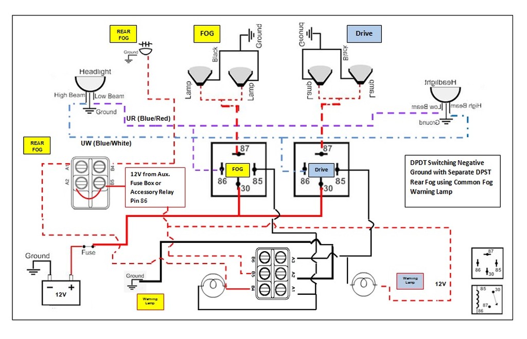
Precisely why I asked the question - it didn't look right. This is what I was thinking - power to the dpdt for the rear fog dashboard warning lamp is taken from the accessory fuse box (the 2nd fuse box) so that the dpdt switch is now separated from the heavier current passing through the fog relay (when activated).
As I see it now, and I hope I've got it right, both switches can now independently illuminate the single dashboard warning lamp for the fog light(s) - rather than have 2 dashboard lamps (one for front fogs, one for rear fog); the rear fog lamp is activated by the dpst on the left (which is connected to the 2nd fuse box which runs off of a relay) and the front fog lamps are activated by the dpdt switch in the center.
My switches are rated at 35A, so it's not the concern that I'll ruin a switch, I just want this to be done right.
The peasants are revolting... ![]()
"Gone with the Wind" - a brief yet moving vignette concerning lactose intolerance
|
|
Total posts: 1716
Last post: Oct 18, 2020 Member since:Oct 18, 2011
|
Cars in Garage: 0
Photos: 0 WorkBench Posts: 0 |
I think that's what I said..... I don't know how jegs switches work so didn't comment on that.
My concern was that the diagram shows the high power side of the fog relay being driven from the switch (although I note the switches in my shed are rated at 20A which should be adequate the fogs - but it kinda negates the whole idea of using relays... does it not??). I would use the same power source for the fog relay as the driving lights.
Cheers, Ian
|
|
Total posts: 5840
Last post: Nov 1, 2019 Member since:Nov 12, 1999
|
Cars in Garage: 0
Photos: 0 WorkBench Posts: 0 |
|
Ian
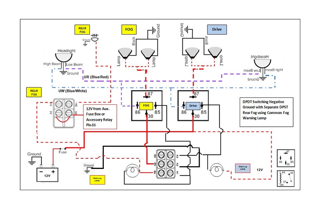
The dual pole switches allow us to have one fog warning lamp activated by circuits for both the front fogs and the rear fogs. Note that in Denmark this indicator lamp is required. The dual pole switches allow throwing the switch to activate two circuits, one grounding the #85 on the relay and the other powering the fog lights on indicator lamp.
The switches can get their +12V from anywhere, but they will have very little draw. My concern would be To make the system neat and tidy. In reality, the fog lights and driving lights are at the front of the car, the relays are on the inner fender, and all that is needed to travel through the firewall is the ground wires coming out to trigger the relays and the power that comes in to power the rear fog lamp, and that then goes up the windshield post like the rest of the harness to the rear. I hope. In my mind, that would be an ideal source for power for the hot side of the DPDT switch that powers the indicator. The heavy wire that goes to #30 need not feed the rear fog or the hot side of the switch.
|
|
Total posts: 1716
Last post: Oct 18, 2020 Member since:Oct 18, 2011
|
Cars in Garage: 0
Photos: 0 WorkBench Posts: 0 |
Hi jeg, this really needs to be done over a coupe of beers,...
I have been ignoring your diagrams , largely because I've ben too lazy to chase all teh wires... and I haven't understood some of the symbology you use.
However, the question above leads me to the view that you don't really understand relays...
A relay is nothing more than an electro/mechanical switch. They have a low powered "switch" side and a high powered delivery side.
I'm using the relay schematic in the bottom right hand corner of your latest diagram as the reference.
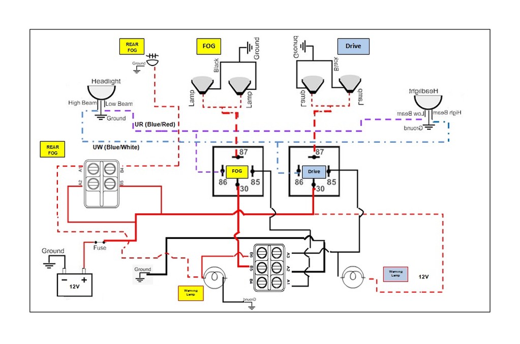
Terminals (T) 85 and 86 are the low powered switched side. They are attached to 12v and earth (not sure which is which but it doesn't really matter). When the 12v is supplied to T 85 or 86 by closing the external switch (on the power or earth side), the relay will activate and close the connection between terminals 87 and 30 allowing power to flows from the (high) powered source (the solenoid/battery) to the live side of the accesory (eg driving light). If the other side of the accesory (teh light) is connected to earth the light will illuminate... There is no connection between 85/86 and 30/87 beyond the magnetic activation of the 30/87 circuit.
The driving light relay in your diagram is correctly wired.
However, you need to feed the fog relay (T30) directly from the battery/power source. The live side of the relay switch circuit is fed from the low beam headlight (when switched on) and earthed through the (six dot??) switch. That way the switch only sees a small current flow (enough to activate the realy) while the fog light is fed the full 12V at 5+A (allowing for a 65W bulb) from the battery. By using the correct symbology you can properly trace the circuits through the A1 to B6 terminals on the switch.... where upon it should all become obvious ![]() (The error in the fog light warning switch circuitry would also then become clear...)
(The error in the fog light warning switch circuitry would also then become clear...)
Cheers, Ian
|
|
Total posts: 7075
Last post: Nov 5, 2019 Member since:Apr 25, 2000
|
Cars in Garage: 0
Photos: 0 WorkBench Posts: 0 |
|
Mur, in the above diagram, the red lead (thick) on dpdt switch B5 doesn't need to be connected to the #30 of the relay, does it? (You can hear that I'm a bit nervous in connecting it to the same #30 big current terminal on the fog and driving lamp relays.)
Could I connect it to the same accessory + (2nd fusebox) that I'm using for the dpst on-off switch used for the rear foglamp?
One set of lamps arrived today, package with switches should arrive tomorrow!
The peasants are revolting... ![]()
"Gone with the Wind" - a brief yet moving vignette concerning lactose intolerance
|
|
Total posts: 7075
Last post: Nov 5, 2019 Member since:Apr 25, 2000
|
Cars in Garage: 0
Photos: 0 WorkBench Posts: 0 |
|
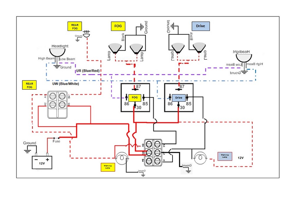
Ok, so even though we've got the 'battery' connected to relay pins #30 and the center of our DPDT switch, there won't be any big draw through the switch when the relay is directing current to the lights? The switch provides the ground and it's also now in the path of the device, not 'diverted' by the relay.
By the way - I'm over 50 ~
The peasants are revolting... ![]()
"Gone with the Wind" - a brief yet moving vignette concerning lactose intolerance
|
|
Total posts: 5840
Last post: Nov 1, 2019 Member since:Nov 12, 1999
|
Cars in Garage: 0
Photos: 0 WorkBench Posts: 0 |
|
Switching the ground to trigger the relay is identical in current to switching the hot, and since it is only a small electromagnet coil it is hardly any draw. Remember that positive earth cars switch all the grounds.
You have one switch that triggers two light systems that depend on two other light systems before they can work, in a logic kind of sequence. Then you have another switch that controls a third light system, and it shares a warning lamp with one of the others. You are accomplishing cool stuff.
When I was 16 and a relay was first described to me, I had trouble understanding it.
|
|
Total posts: 7075
Last post: Nov 5, 2019 Member since:Apr 25, 2000
|
Cars in Garage: 0
Photos: 0 WorkBench Posts: 0 |
|
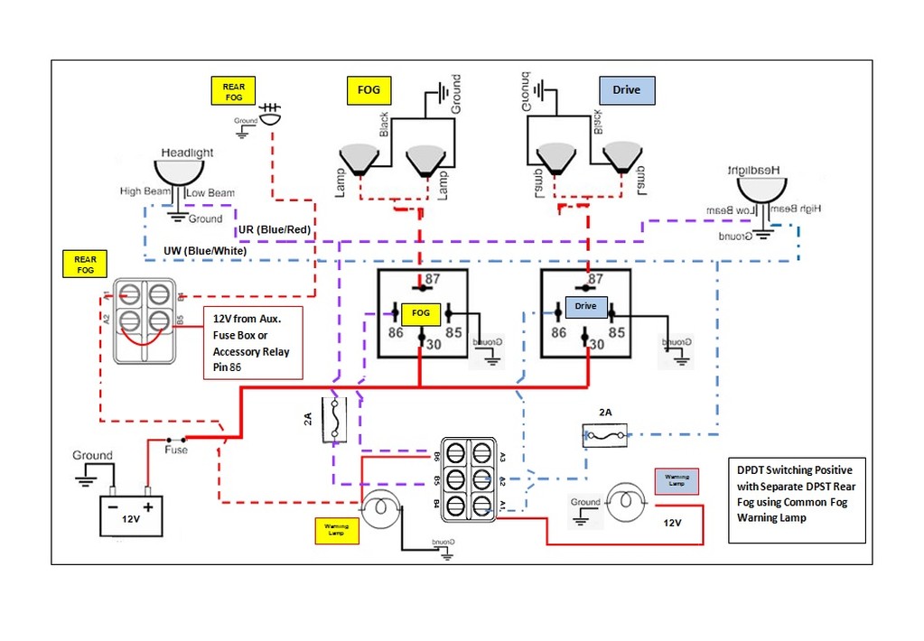
I also wonder, now that I've learned a few things, if this wouldn't be more suitable for anyone who lacks these spiffy 35A switches that I'm fortunate to have. It seems to me that by switching the circuit's ground, we'd be putting more current through the switch when the circuit is closed and that 'a lesser switch' wouldn't be able to carry the current and risk overload.
If I've got it right, this new drawing is intended to be a more traditional 'switching the positive' and grounding the relays directly. I assume also that a spdt switch could also be used in lieu of the dpdt.
Am I right in thinking this?
The peasants are revolting... ![]()
"Gone with the Wind" - a brief yet moving vignette concerning lactose intolerance
|
|
Total posts: 7075
Last post: Nov 5, 2019 Member since:Apr 25, 2000
|
Cars in Garage: 0
Photos: 0 WorkBench Posts: 0 |
|
Something wasn't right with the previous fog lamp/warning lamp switching, so I changed a few things on the DPDT switch. I think this will be easier to read, understand and execute; not to mention illuminate the fog warning lamp correctly when in the 'fog' position. The previous version is ...long_title #3, new version is #5.
The peasants are revolting... ![]()
"Gone with the Wind" - a brief yet moving vignette concerning lactose intolerance
|
|
Total posts: 7075
Last post: Nov 5, 2019 Member since:Apr 25, 2000
|
Cars in Garage: 0
Photos: 0 WorkBench Posts: 0 |
|
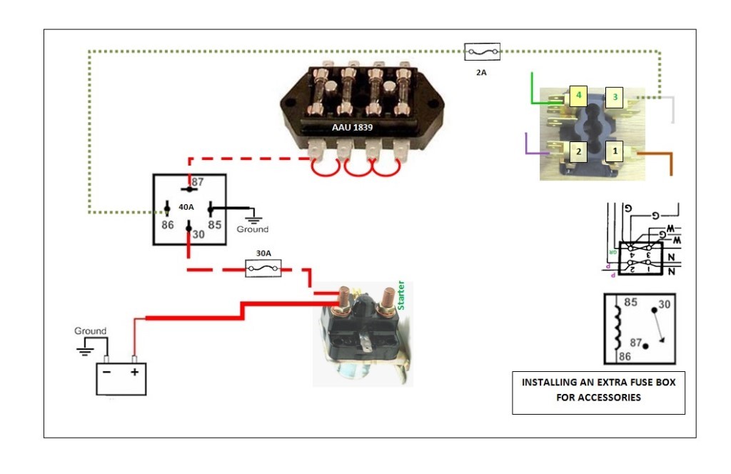
Thank you!
I'll change my 2nd fuse box to this installation which will allow added accessories to be 'automatically' relay installed. The 40A relay should be big enough to serve the radio, fuel pump, air-fuel meter and anything else that get added.
The peasants are revolting... ![]()
"Gone with the Wind" - a brief yet moving vignette concerning lactose intolerance
|
|
Total posts: 5840
Last post: Nov 1, 2019 Member since:Nov 12, 1999
|
Cars in Garage: 0
Photos: 0 WorkBench Posts: 0 |
|
Nice!
You are getting good at this.
|
|
Total posts: 7075
Last post: Nov 5, 2019 Member since:Apr 25, 2000
|
Cars in Garage: 0
Photos: 0 WorkBench Posts: 0 |
|

I'm not sure if I've got it, but have added a dpst for the rear fog lamp -
The peasants are revolting... ![]()
"Gone with the Wind" - a brief yet moving vignette concerning lactose intolerance
|
|
Total posts: 5840
Last post: Nov 1, 2019 Member since:Nov 12, 1999
|
Cars in Garage: 0
Photos: 0 WorkBench Posts: 0 |
|
Nope. I am crushing my coloured markers with the back tires of the Lexus.
OK. Most of your diagram is correct, except add the DPST switch to the rear fog lamp. Power comes to the switch and goes to both source posts. One post that is hot when the switch is thrown powers the dash indicator lamp and the other powers the rear fog lamp. We are trying to do the same thing that having two sides did for the front fog lights.
Maybe I will find some markers tomorrow and do a diagram. Also, can you do another diagram of the auxilliary circuits relay for the other wiring thread? Yours are pretty.


