
| Orig. Posting Date | User Name | Edit Date |
| Jan 22, 2015 05:25PM | jeg | Edited: Jan 22, 2015 05:38PM |
| Jan 21, 2015 08:31PM | mur | |
| Jan 21, 2015 08:12PM | jeg | |
| Jan 21, 2015 08:10PM | mur | |
| Jan 21, 2015 08:02PM | mur | |
| Jan 21, 2015 05:31PM | jeg | |
| Jan 21, 2015 04:02PM | jeg | |
| Jan 21, 2015 03:59PM | mur | |
| Jan 21, 2015 03:49PM | jeg | |
| Jan 20, 2015 06:49PM | mur | |
| Jan 20, 2015 03:22PM | jeg | |
| Jan 17, 2015 09:50AM | jeg | Edited: Jan 21, 2015 06:06PM |
| Jan 16, 2015 11:05AM | mur | |
| Jan 16, 2015 08:22AM | malsal | |
| Jan 16, 2015 07:50AM | jchealey | |
| Jan 16, 2015 06:52AM | MtyMous | |
| Jan 16, 2015 02:23AM | HOT | |
| Jan 16, 2015 12:59AM | jeg | Edited: Jan 16, 2015 01:18AM |
| Jan 16, 2015 12:29AM | 1963SV2 | |
| Jan 16, 2015 12:27AM | mur |

|
Total posts: 7075
Last post: Nov 5, 2019 Member since:Apr 25, 2000
|
Cars in Garage: 0
Photos: 0 WorkBench Posts: 0 |
|
The parts are pouring in, hope to get into the garage next week for the installation and general wiring cleanup. The 1st package from VWP (UR/UW 25A wire, 6.3mm latched relay socket terminals, different sized ring terminals, a few in-line splashproof fuse holders (just like mur's), triple snap (bullet) connectors, etc. arrived today, the 2nd with the junction box and a few odds & ends was sent today, Danish customs asked for a copy of the invoice from my driving lamp order (they want to verify that I ordered them), the fogs arrived at my brother's house and he'll send them together with the relay sockets (can't get the Hella like I have already here in DK, so he'll send them with the lamps.)
HOWEVER - there might be a problem. I took my wife's car in for MOT (well, over here it's known as 'Syn') today and the inspection guy and I were talking. He's a mini guy from way back, loves my mini and so I continue to use his facility. I told him that I was installing accessory lighting and he explained that it's necessary to have warning lights on the dash. I told him, Yep - have them from when I installed the rear fog lamp.
That's when the cookie crumbled. Apparently, not only do I need to have the warning lights, but also be able to operate the rear fog lamp independently of the front fog lamps (used in conjunction with low-beams); we can't use both unless severe weather conditions allow it, then the 2nd light can be activated. So, since the rear fog lamp gets used more than front fogs, we need to adapt the drawing to accomodate.
So - any ideas? I have an additional spst (2-terminal on-off) switch that I can add to the system, and can get a 5-terminal (w/87a) relay if needed, could also possibly stretch to order a dpdt (6-terminal on-off-on) switch just before Hyacinth kicks me on the street.
I'd like some more help please - E-mail in profile if necessary -
 The peasants are revolting...
 ![]()
"Gone with the Wind" - a brief yet moving vignette concerning lactose intolerance
|
|
Total posts: 5840
Last post: Nov 1, 2019 Member since:Nov 12, 1999
|
Cars in Garage: 0
Photos: 0 WorkBench Posts: 0 |
|
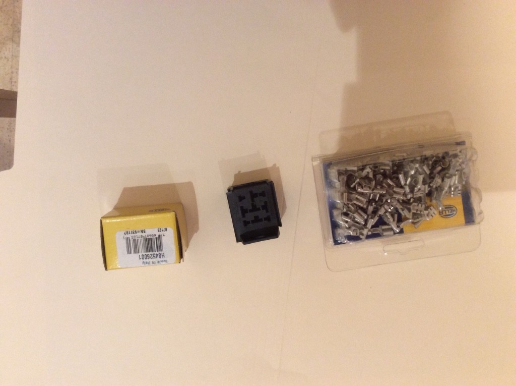
Lastly, an image of the terminals that fit in a relay block. A guy rebuilding a mini nearby wants an original look to his relays so he will get custom ones with wire recycled from an old harness in the right colours. Multiple blocks can be connected, and these terminals should be carefully crimped with the correct die for double barrel crimps. There is a crimp on the wire and on the insulation, which counters the terminal failures that result from vibration. I know, I talked about this in posts years ago.
|
|
Total posts: 7075
Last post: Nov 5, 2019 Member since:Apr 25, 2000
|
Cars in Garage: 0
Photos: 0 WorkBench Posts: 0 |
|
Thanks - nice picture, says a lot. I really look forward to assembling this.
The peasants are revolting... ![]()
"Gone with the Wind" - a brief yet moving vignette concerning lactose intolerance
|
|
Total posts: 5840
Last post: Nov 1, 2019 Member since:Nov 12, 1999
|
Cars in Garage: 0
Photos: 0 WorkBench Posts: 0 |
|
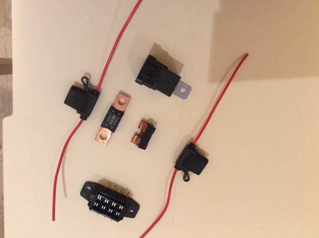
Next I have a fun selection. That black thing is a breaker that fits where the old school glass fuses fit. There are two excellent quality in line hooded fuse holders. There is a Littlefuse 175 amp fuse, something you might use for an inverter, but this would not allow starter current over the long term so not something to protect the entire car. There is a brand new relay that would fit the pigtail above. There is also a Hella fuse box that could fuse four circuits. Note how some folks think that this might replace their original four fuse mini fuse box, but of course it is not a fuse and junction box like the Lucas item. Next time I am rich I will buy a new Lucas box just to have one on hand! Then I will fill it with breakers. You can also get automatic and manual reset circuit breakers to go in where blade type fuses go. On both the MK IV onward Lucas box and this Hella box, fitting breakers means that the cover will not go on.
|
|
Total posts: 5840
Last post: Nov 1, 2019 Member since:Nov 12, 1999
|
Cars in Garage: 0
Photos: 0 WorkBench Posts: 0 |
|

I took a few photos. Sorry that they show up upside down sometimes. First is a slightly used relay that was recently on a mini with a solenoid mounted on the starter. Note that the normally closed circuit wire is still present. Beside it is a brand new pigtail. Note the seal. The blue wire takes the bullet male from the wiring harness, either UW or UR and the bullet on the large red wire comes from 87B the normally open terminal. 30 is another thick red wire, and has a ring terminal. Ground and trigger 85 and 86, are thin wires. You can go to even 22 gauge but I probably wouldn't buy anything smaller than 14.
|
|
Total posts: 7075
Last post: Nov 5, 2019 Member since:Apr 25, 2000
|
Cars in Garage: 0
Photos: 0 WorkBench Posts: 0 |
|
Right - ordered the junction box, some wire sleeving and a few other odds & ends; a couple of extra relay sockets, pair of extra relays for the 'spares box'. (It ($) adds up quick when shopping)
The only thing I'm a bit unsure of is how heavy the ground wires at the switch should be (all 3).
If I've got this right, the 12V+ wires to the #30 and relay #87 pins to the lamps need to be 'heavy' (I've ordered striped 25 Amp thinwall 28/0.30 2mm sq.) , and the #86 & #85 ground (to switch terminals) can be lightweight (16.5 Amp thinwall 32/0.20 1mm sq.).
If this is correct, I should probably adjust the drawing to thinner lines where applicable...
The peasants are revolting... ![]()
"Gone with the Wind" - a brief yet moving vignette concerning lactose intolerance
|
|
Total posts: 7075
Last post: Nov 5, 2019 Member since:Apr 25, 2000
|
Cars in Garage: 0
Photos: 0 WorkBench Posts: 0 |
|
You da man -
I'll order the junction box forthwith.
The peasants are revolting... ![]()
"Gone with the Wind" - a brief yet moving vignette concerning lactose intolerance
|
|
Total posts: 5840
Last post: Nov 1, 2019 Member since:Nov 12, 1999
|
Cars in Garage: 0
Photos: 0 WorkBench Posts: 0 |
|
That looks sharp. Buy a few non nylok nuts to place between ring terminals. I will take some photos of stuff tonight. Here is the wiring I did today:
|
|
Total posts: 7075
Last post: Nov 5, 2019 Member since:Apr 25, 2000
|
Cars in Garage: 0
Photos: 0 WorkBench Posts: 0 |
|
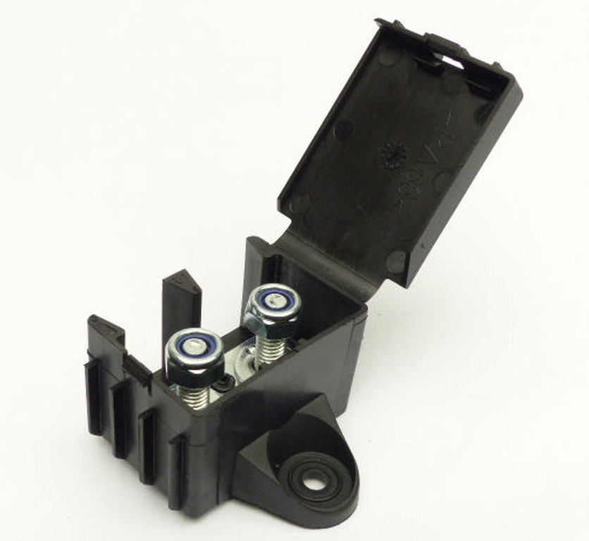
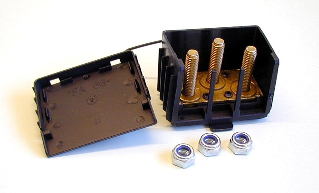
Cool - what do you think of something like this to be able to 'extend' the solenoid stud? I'm thinking that while I'm doing this installation, maybe I can clean-up and streamline the older installations a bit.
The peasants are revolting... ![]()
"Gone with the Wind" - a brief yet moving vignette concerning lactose intolerance
|
|
Total posts: 5840
Last post: Nov 1, 2019 Member since:Nov 12, 1999
|
Cars in Garage: 0
Photos: 0 WorkBench Posts: 0 |
|
I think you might find that type of fuse holder to be a bit weak. I would often run out of the good quality ones I would buy in bulk and have to buy holders at auto parts stores: those are a bit stiff and it is hard to open the hood if it is cold. Furthermore, it will be hard to keep things neat. I personally don't fuse or breaker relays any more as the relay will then become the fuse. Indeed I had an issue with one of my heavy trucks where a solenoid started to draw more power due to age, and then the relay supplying it failed while the fuse did not blow. This was on a fail safe electric over hydraulic over mechanical parking brake. A little awkward. In any case, maybe a breaker with two #10 screw posts would work well for your application. You could get a 30 amp one, and then feed all of your relays from there, one wire from the. Solenoid to the auto reset breaker, and then wires to each relay or wire them in a chain.
|
|
Total posts: 7075
Last post: Nov 5, 2019 Member since:Apr 25, 2000
|
Cars in Garage: 0
Photos: 0 WorkBench Posts: 0 |
|
Woohoo!
Just received an E-mail that the foglamps are finally shipped! Lamp bar arrived yesterday, wire stock from VWP should arrive tomorrow, driving lamps arrived at the Copenhagen customs facility this afternoon. With any luck, I'll be puttering in the garage next weekend!
The peasants are revolting... ![]()
"Gone with the Wind" - a brief yet moving vignette concerning lactose intolerance
|
|
Total posts: 7075
Last post: Nov 5, 2019 Member since:Apr 25, 2000
|
Cars in Garage: 0
Photos: 0 WorkBench Posts: 0 |
|
Yes, I plan on taking power from the post on the starter solenoid, provided that there's enough space for another ring terminal. I need to check, but I believe I've 3 on there already and the post isn't really that long. I've got some ring terminals with different bore sizes coming along with the wire from VWP , so if necessary, maybe I can crimp 2 of the FH440 Wired Blade Fuse Holder onto the same ring. And, maybe the bores are big enough that I can alter what I've got mounted to the solenoid already.
I'm thinking that after I've got these things in place, maybe a tidying up will be in order. There seem to be more than a few 6mm PVC sleeves that contain only 2 wires; maybe I can take a look and see what's what and if I can combine pairs that go to the same device. Since I've used 'correct' striped wires, it might be possible.
Thanks for all your help and suggestions. Even though the parts aren't here yet, I really appreciate it. I feel much more confident and have the installation well rehearsed. Your advice also gives the opportunity to re-visit some of my earlier upgrades and installations, perhaps with a view to streamlining them. Cool stuff...
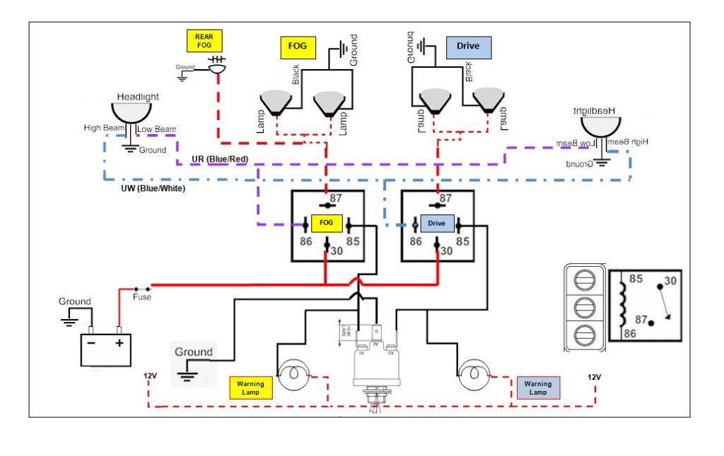
Edit: Learned the following, so adjusted the drawing accordingly:
DIN 72552 defines contact numbers in relays for automotive use:
- 85 = relay coil -
- 86 = relay coil +
- 87 = common contact
- 87a = normally closed contact
- 87b = normally open contact
The peasants are revolting... ![]()
"Gone with the Wind" - a brief yet moving vignette concerning lactose intolerance
|
|
Total posts: 5840
Last post: Nov 1, 2019 Member since:Nov 12, 1999
|
Cars in Garage: 0
Photos: 0 WorkBench Posts: 0 |
|
I think the battery in the diagram is just a handy image for the 12 V source and the relays will get their power from the solenoid just like the other relays already fitted to his car.
|
|
Total posts: 8382
Last post: Jan 13, 2022 Member since:Feb 7, 2006
|
Cars in Garage: 0
Photos: 0 WorkBench Posts: 0 |
|
I relayed mine (with help from a friend who actually likes electrical work) off the sidelight circuit and through the rear fog light switch, it seems to work fine and was easy peasy.
If in doubt, flat out. Colin Mc Rae MBE 1968-2007.
Give a car more power and it goes faster on the straights,
make a car lighter and it's faster everywhere. Colin Chapman.
|
|
Total posts: 358
Last post: Feb 20, 2020 Member since:Jul 20, 2013
|
Cars in Garage: 0
Photos: 0 WorkBench Posts: 0 |
Jerry
|
|
Total posts: 2277
Last post: Oct 6, 2022 Member since:Nov 18, 2007
|
Cars in Garage: 0
Photos: 77 WorkBench Posts: 2 |
|
Jeg, I had a very similar diagram built in Visio, but I fell asleep with my computer in my lap while I was making it. Haha. Woops. But the only real diference I had on mine was that pin 85 was the ground instead of 86. That's just personal as I like uniformity in my relays. Makes no difference here. Looks like a solid plan to me. I would just try to minimize wire length. And keep the ground wires as short as possible.
Mur, I agree that wiring from the starter solenoid directly is a good idea, but if he ran a heavy enough gauge directly to the battery, it wouldn't make a difference. The effective length of the circuit is just as long when wired to the solenoid or directly to the battery. Just the solenoid to battery wire is much heavier gauge.
But I do agree with wiring to the solenoid. Cleaner install.
|
|
Total posts: 37
Last post: May 25, 2015 Member since:Dec 26, 2014
|
Cars in Garage: 0
Photos: 0 WorkBench Posts: 0 |
Nice diagram 
May I add one more improvement?
To make the installation easier and save you from running a wire all the way from the battery to the relays, I´d suggest to connect that fused life feed with a ring terminal directly to the battery terminal of the starter solenoid, where all the life feeds are connected anyways.
This will also make the lights brighter! As the shorter the wire, the lower the resistance 
Cheers,
Diddi
|
|
Total posts: 7075
Last post: Nov 5, 2019 Member since:Apr 25, 2000
|
Cars in Garage: 0
Photos: 0 WorkBench Posts: 0 |
|
I kinda did that intentionally. I'll get power for those from the dashboard illumination circuit, as it's serving the gauges right below them. You are right of course, they should be there, so in the interest of completeness I'll stick a little pigtail off of the diagram boxes.
The diagram above is edited to the latest version -
The peasants are revolting... ![]()
"Gone with the Wind" - a brief yet moving vignette concerning lactose intolerance
|
|
Total posts: 1716
Last post: Oct 18, 2020 Member since:Oct 18, 2011
|
Cars in Garage: 0
Photos: 0 WorkBench Posts: 0 |
Your diagram is also missing a power line to the warning lights....
Cheers, Ian
|
|
Total posts: 5840
Last post: Nov 1, 2019 Member since:Nov 12, 1999
|
Cars in Garage: 0
Photos: 0 WorkBench Posts: 0 |
|
If the battery is disconnected, either by the + cable being removed or switched off, or the - the result is the same. You would not be able to measure voltage anywhere. I just enjoy a good solid switched ground, as my first mini was positive earth! I do like that you have that plan to not molest the original harness.


