
| Orig. Posting Date | User Name | Edit Date |
| Jan 23, 2015 09:15PM | mur | |
| Jan 23, 2015 09:12PM | DS1980 | |
| Jan 23, 2015 08:59PM | mur | |
| Jan 23, 2015 08:57PM | DS1980 | |
| Jan 23, 2015 08:47PM | 1963SV2 | |
| Jan 23, 2015 08:25PM | DS1980 | |
| Jan 22, 2015 06:11AM | Dan Moffet | Edited: Jan 22, 2015 06:14AM |
| Jan 22, 2015 05:54AM | Dan Moffet | |
| Jan 20, 2015 08:12PM | MPlayle | |
| Jan 20, 2015 07:08PM | DS1980 | Edited: Jan 20, 2015 07:10PM |
| Jan 20, 2015 04:43PM | 1963SV2 | |
| Jan 20, 2015 03:40PM | Cup Cake | Edited: Jan 20, 2015 03:41PM |
| Jan 20, 2015 03:33PM | DS1980 | Edited: Jan 24, 2015 11:47PM |

|
Total posts: 5840
Last post: Nov 1, 2019 Member since:Nov 12, 1999
|
Cars in Garage: 0
Photos: 0 WorkBench Posts: 0 |
|
8 amps will certainly add a load! The fuse will protect things, but it won't make a load not draw current.
|
|
Total posts: 188
Last post: Dec 8, 2016 Member since:Mar 5, 2011
|
Cars in Garage: 0
Photos: 0 WorkBench Posts: 0 |
|
Hi again Mur, good to hear from you.
It's been mentioned that if I add an inline fuse just after the fusebox than this will not increase the load on that circuit. Is this correct? This will be for a fan drawing a max of 8 amps.
I did read that threrad, and really hope it's not that complicated.
|
|
Total posts: 5840
Last post: Nov 1, 2019 Member since:Nov 12, 1999
|
Cars in Garage: 0
Photos: 0 WorkBench Posts: 0 |
|
In reality, you should NOT add any load to the original wiring harness. Yes, the manual was suggesting a fair method at the time but these days it would be much simpler to build auxiliary circuits into the car that have minimal impact on the original hardware.
Look to the lengthy thread started by Jeg about: electrical question. He is doing several non original things, but his initial work was to add a simple four fuse fuse block powered directly from the starter solenoid via a relay. The relay was triggered by the ignition being turned on. In this way, none of the new circuits add any load to the original wiring. To accomplish this, you would need to connect one wire to the car's fuse box. This wire would be an in line fuse holder with a very low amperage fuse, and you would connect it to the white ignition wire that is discussed above. It would have a fuse so that nothing could happen to it that might impair the car's ignition circuit. This would go to the terminal #86 of the relay, #85 would go directly to a ground, #30 would go to the main post from the battery to the starter solenoid, perhaps via a fuse or breaker, and lastly #87b would go to the source side of the fuses on the fuse box.
The benefits of this are obvious, but the real advantage is that you will learn what a relay is and does and then you will be able to go to the auto parts store and get a few more relays, one for the headlamp high beams, one for the low beams, and one for a really awesome Fiamm horn.
|
|
Total posts: 188
Last post: Dec 8, 2016 Member since:Mar 5, 2011
|
Cars in Garage: 0
Photos: 0 WorkBench Posts: 0 |
|
Oh, so 1 and 3 (the terminals prior to the fuses) are the unfused circuits. I thought everything went out of 2 and 4, I didn't think of current flow out of 1 and 3. Thanks!
|
|
Total posts: 1716
Last post: Oct 18, 2020 Member since:Oct 18, 2011
|
Cars in Garage: 0
Photos: 0 WorkBench Posts: 0 |
On my Mini 1 and 3 are connected by the fuse (or maybe its 1 and 2 - they're not actually numbered).
In any case (lets assume the ones connected by the fuse are 1 and 3)... If the fuse blows then 3 is dead ...but any thing connected from 1 to earth is still alive. Hence fused/unfused....
Cheers, Ian
|
|
Total posts: 188
Last post: Dec 8, 2016 Member since:Mar 5, 2011
|
Cars in Garage: 0
Photos: 0 WorkBench Posts: 0 |
|
OK, I think I'm getting this. I would like it to be switched, so I'm going to run it out of a connector from terminal 4, to an inline fuse, to the accessories plug, then to ground.
However, I still do not understand this statement: "If you add an accessory and want it switch controlled, connect it to the unfuse/switched terminal and put an inline fuse close to the fusebox." The fuse box links terminals 1 and 3, all of which run through a fuse, and terminals 2 and 4, which all run through a fuse, so I do not understand the "unfused/switched terminal." I see terminal 4 as only being a fused terminal.
|
|
Total posts: 9542
Last post: Apr 18, 2024 Member since:Aug 14, 2002
|
Cars in Garage: 0
Photos: 0 WorkBench Posts: 0 |
|
Your 2-fuse box should have a brown wire (power feed) coming from the solenoid to terminal 1. There will likely be other brown wires carrying current on to other places. The opposed side of that fuse, terminal 2 should have a couple of purple wires going away. Terminal 3 should have white wires connected to it. One comes from the igniton switch "on" terminal. (The ignition switch gets power directly from the solenoid terminal from one of the other brown wires attached to it.) One of the other white wires coming away from terminal 3 goes to the coil - unfused because you wouldn't want a fuse to blow and kill the engine. Terminal 4 should have green wires attached to it, going to places like windshiel wiper switch, brake light switch, etc. As noted lots of other wires might have been addded in the car's previous life.
.
"Hang on a minute lads....I've got a great idea."
|
|
Total posts: 9542
Last post: Apr 18, 2024 Member since:Aug 14, 2002
|
Cars in Garage: 0
Photos: 0 WorkBench Posts: 0 |
|
The 4 terminals on an (early - don't know what happened post 76) Mini are fused switched, fused unswitched, unfused switched and unfused unswitched....
Using a test light (easy to make one - I bought mine for $2 at the local auto shop) it only takes a few minutes to work out which is which.
Then you decide which you want to drive your accessory plug. I chose unfused/unswitched because sometimes I might want the accessory on while the ignition is off (so I fitted a separate switch) and I also chose a differently valued fuse for the accessory rather than the standard 30A Mini fuse....
As a rule I don't trust wire colours or diagrams because you never know what those POs may have done in the period between the manual being printed and you acquring the car .... and it only takes a few minutes to check.
Cheers, Ian
As Ian says, it depends on whether you wan the ignition switch to control power to the accessory.
Connecting it via the ignition switch has the advantage of not leaving the accessory on and draiingthe battery, but has the disadvantage that the load is going through the ignition switch (unless you are into relays etc.) That adds current to the circuit all the way to the fuse box and through that fuse. It was originally rated at 30A to carry all the original loads applied to it. Bear in mind that none of the wire coming away from that fuse can individually carry 30A - you can let alot of smoke out of one of those wires before the fuse blows.
If you add an accessory and want it switch controlled, connect it to the unfuse/switched terminal and put an inline fuse close to the fusebox. If you want it un-switched, then conect it to the unfused/unswitched terminal and provide an inline fuse for the accessory. In either case you are not adding load on the fusebox fuses.
Later 4-fuse boxes partially solved the problem by adding two more fuses, one of which is switched for heater fan, wipermotor etc, and the other is unswitched for lights, horn etc. Then depending on year, market (export, Europe etc.) there are several factory inline fuses, sometimes well hidden. In my car, I still don't think I know for sure what all they do...
.
"Hang on a minute lads....I've got a great idea."
|
|
Total posts: 1787
Last post: Mar 26, 2024 Member since:Feb 1, 2000
|
Cars in Garage: 0
Photos: 0 WorkBench Posts: 0 |
|
|
|
Total posts: 188
Last post: Dec 8, 2016 Member since:Mar 5, 2011
|
Cars in Garage: 0
Photos: 0 WorkBench Posts: 0 |
|
Ah, check the wiring diagram. And look at that, terminal 4 is right there. I tried to not ask a dumb question. Did not work.
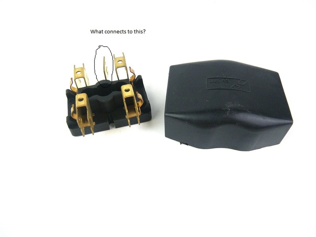
One last one. There is a terminal between one and three. The wiring diagram does not show this terminal. What connects into this?
|
|
Total posts: 1716
Last post: Oct 18, 2020 Member since:Oct 18, 2011
|
Cars in Garage: 0
Photos: 0 WorkBench Posts: 0 |
The 4 terminals on an (early - don't know what happened post 76) Mini are fused switched, fused unswitched, unfused switched and unfused unswitched....
Using a test light (easy to make one - I bought mine for $2 at the local auto shop) it only takes a few minutes to work out which is which.
Then you decide which you want to drive your accessory plug. I chose unfused/unswitched because sometimes I might want the accessory on while the ignition is off (so I fitted a separate switch) and I also chose a differently valued fuse for the accessory rather than the standard 30A Mini fuse....
As a rule I don't trust wire colours or diagrams because you never know what those POs may have done in the period between the manual being printed and you acquring the car .... and it only takes a few minutes to check.
Cheers, Ian
|
|
Total posts: 10335
Last post: Aug 19, 2016 Member since:May 13, 2001
|
Cars in Garage: 0
Photos: 0 WorkBench Posts: 0 |
|
Look at the wiring diagram for your car to see what wires are hooked up to terminal 4. On a MkI there're two, a green and a green/purple. Also if you look closely the terminals are numbered on the fuse box.
The power of accurate observation is commonly called cynicism by those who have not got it. G.B.S. Sarcasm is the lowest form of wit. Oscar Wilde
//www.cupcakecooper.ca/
|
|
Total posts: 188
Last post: Dec 8, 2016 Member since:Mar 5, 2011
|
Cars in Garage: 0
Photos: 0 WorkBench Posts: 0 |
|
Hello,
Trying to figure out how to wire a 12 volt socket into my mini. The book says to wire all additional accessories into terminal 4, but does not specify which is termanal 4 on the older 2-fuse fuseboxes. Any help is appreciated.


