
| Orig. Posting Date | User Name | Edit Date |
| Jan 31, 2015 04:12PM | jeg | |
| Jan 30, 2015 07:15PM | jeg | Edited: Jan 31, 2015 05:17PM |
| Jan 29, 2015 06:21PM | 1963SV2 | |
| Jan 29, 2015 04:21PM | mur | |
| Jan 29, 2015 04:14PM | mur | |
| Jan 29, 2015 07:06AM | rb92673 | |
| Jan 28, 2015 09:29PM | 1963SV2 | |
| Jan 28, 2015 07:31PM | mur | |
| Jan 28, 2015 07:12PM | 1963SV2 | Edited: Jan 28, 2015 09:20PM |
| Jan 28, 2015 06:30PM | mur | |
| Jan 28, 2015 03:34PM | rb92673 | |
| Jan 28, 2015 01:44PM | mur | |
| Jan 28, 2015 09:53AM | rb92673 | |
| Jan 27, 2015 06:04PM | 1963SV2 | |
| Jan 27, 2015 04:46PM | jeg | |
| Jan 27, 2015 04:35PM | 1963SV2 | |
| Jan 27, 2015 04:29PM | jeg | |
| Jan 27, 2015 03:52PM | 1963SV2 | |
| Jan 27, 2015 02:56PM | jeg | |
| Jan 27, 2015 02:46PM | 1963SV2 |

|
Total posts: 7075
Last post: Nov 5, 2019 Member since:Apr 25, 2000
|
Cars in Garage: 0
Photos: 0 WorkBench Posts: 0 |
|
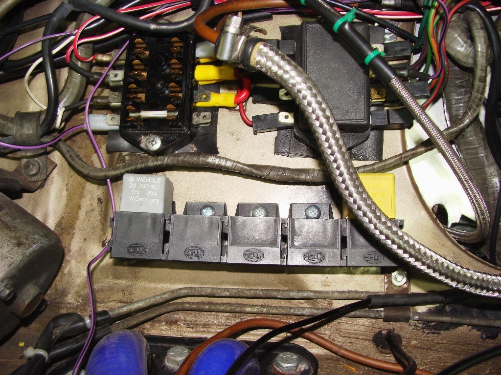

I installed the junction box, removed and reinstalled the 2nd fuse box and installed a few more relay holders today. Additionally, I removed the headlight relays that I'd installed some years ago and re-connected the headlamp loom as it was from the factory.
Hyacinth will allow me to go back into the garage tomorrow, so I shouldn't have any trouble assembling some new wires.
 The peasants are revolting...
 ![]()
"Gone with the Wind" - a brief yet moving vignette concerning lactose intolerance
|
|
Total posts: 7075
Last post: Nov 5, 2019 Member since:Apr 25, 2000
|
Cars in Garage: 0
Photos: 0 WorkBench Posts: 0 |
|
Nice job mur - I threw this together this evening, been busy with looking for work...
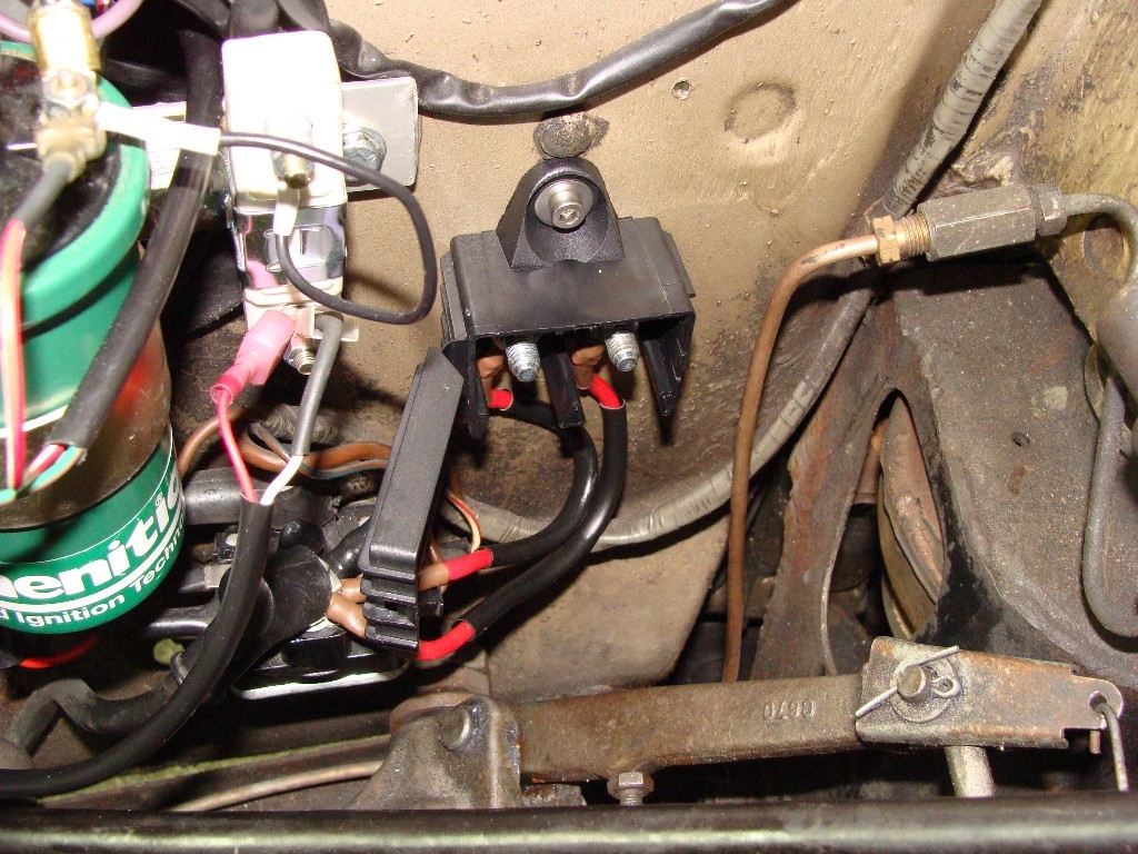
My last box o'auxilliary lighting bits came in the mail today, so I'll be re-wiring my 2nd fuse box, relocating my headlight relays (they're nearly squashed by the Luminition brackelt) and hopefully installing the complete foglamp/driving lamp setup.
It'll be 'Live Action!' in the garage (I'll have the camera with me), so if I remember, I'll take a few snapshots.
The peasants are revolting... ![]()
"Gone with the Wind" - a brief yet moving vignette concerning lactose intolerance
|
|
Total posts: 1716
Last post: Oct 18, 2020 Member since:Oct 18, 2011
|
Cars in Garage: 0
Photos: 0 WorkBench Posts: 0 |
I would expect them to be at least signed for that much ![]()
I was looking for the connection between the A and B side of jeg's switches ..but now realise there isn't one ..... duh
Cheers, Ian
|
|
Total posts: 5840
Last post: Nov 1, 2019 Member since:Nov 12, 1999
|
Cars in Garage: 0
Photos: 0 WorkBench Posts: 0 |
|
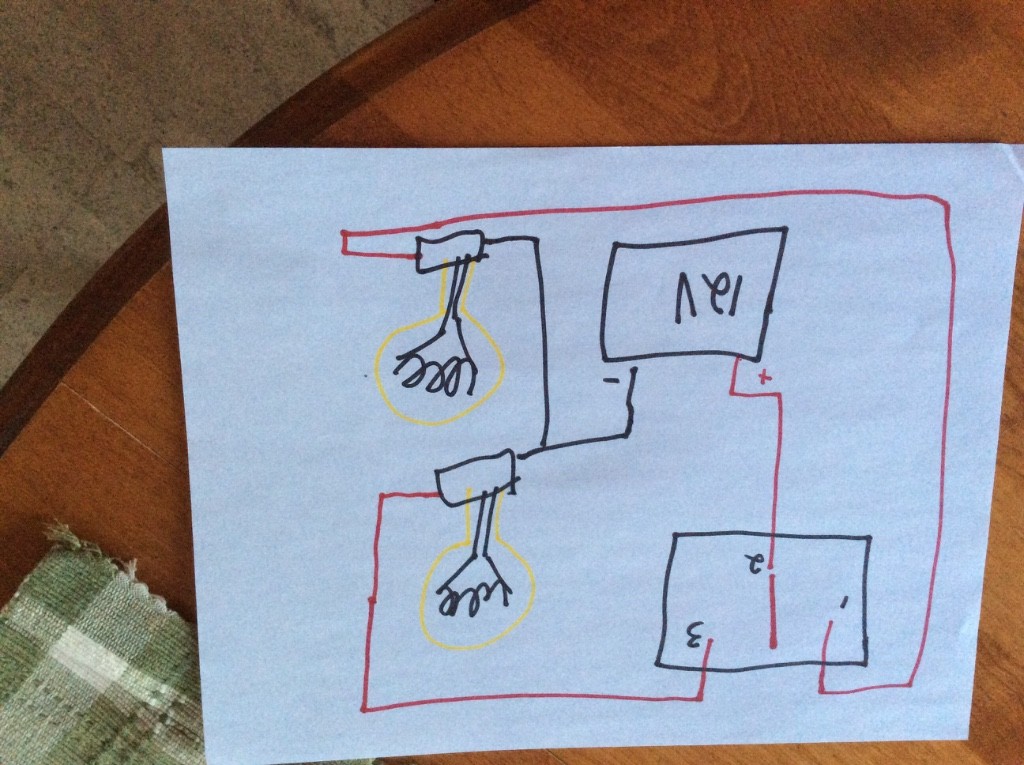
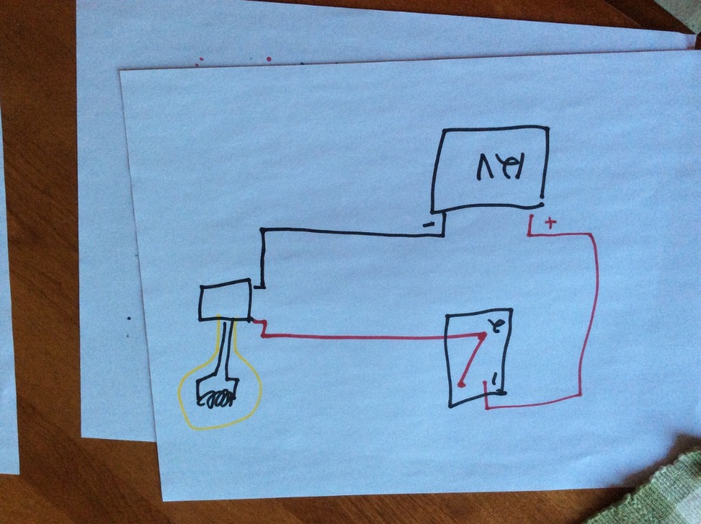
Next is a single pole, dual throw switch, or SPDT. Again, upside down and I suppose it could use a larger palette of colours. When the switch is flicked one way, power flows from 2 to 1 and when switched the other, power flows from 2 to 3, and one bulb or the other lights up.
Now, let's be fair, my images are neither ideal nor correct as far as the architecture of wiring drawing, so I will NOT bother you poor folks with a third image. A dual pole, dual throw or DPDT switch is basically two of these switches getting switched at the same time by only one lever.
Using Google you can get great examples of DPDT switches.
I will be willing to mail these drawings in exchange for Jack Knight 5 speeds or Opcon superchargers.
|
|
Total posts: 5840
Last post: Nov 1, 2019 Member since:Nov 12, 1999
|
Cars in Garage: 0
Photos: 0 WorkBench Posts: 0 |
|
Ian asked for some lousy switch illustrations sourced from me, so here goes. First is a single pole, single throw switch. Easy, everyone knows this. Sure, it is a billion times more complicated because the iPad images go upside down, but whatever. My wife came into the kitchen and asked if I needed more colours.
|
|
Total posts: 157
Last post: Jul 24, 2020 Member since:Aug 28, 2013
|
Cars in Garage: 0
Photos: 0 WorkBench Posts: 0 |
How about you plan to do it on Saturday! At least do ONE relay for the low beams, so that you get a sense of what this is all about, and you can be the poster child for this thread. You can go to a local parts store and buy the relay, maybe a a relay block with a pigtail, an in line fuse holder some wire terminals and some wire, and put it all together Saturday, post a picture or two, maybe have a good look at the horn relay you already have.
I would, but I will be out of town. Perhaps next Saturday.
|
|
Total posts: 1716
Last post: Oct 18, 2020 Member since:Oct 18, 2011
|
Cars in Garage: 0
Photos: 0 WorkBench Posts: 0 |
I agree there are generators ....and generators. I have had similar issues and switched to an alternator... Not because of capacity but because the 40 odd year old generator was no longer generating ![]()
Given a choice I would always go with an alternator but I don't believe in fixing what ain't broke....
BTW - any chance you could sketch the circuitry for the "dpdt" switches depicted in jeg's diagrams please. I have several switches in my handy billy that I'm still trying to sort the gazintas and comeouters...
Cheers, Ian
|
|
Total posts: 5840
Last post: Nov 1, 2019 Member since:Nov 12, 1999
|
Cars in Garage: 0
Photos: 0 WorkBench Posts: 0 |
|
Ian-this is just based on experience from when I was a kid and still ran a generator on my Cooper S.
|
|
Total posts: 1716
Last post: Oct 18, 2020 Member since:Oct 18, 2011
|
Cars in Garage: 0
Photos: 0 WorkBench Posts: 0 |
"An extended trip with H4 headlamps, an electric fuel pump, a heater fan and a points style ignition will quickly discharge the battery as the generator makes less power than the above items will draw..."
I'm not sure I'd agree with that. H4 headlights (say 11A) + fuel pump (5A) + heater fan (10A) + ignition (I don't see points consuming any power beyond some heat loss - the power goes to charging the coil however switched) 2A = 28A IMHO this is an extremely generous budget and well within the capability of a generator (even allowing a few amps for the wipers and a radio... and charging the cell phone![]() .
.
The trouble with generators is that they produce little or no power at idle/low revs. If your trip is cross country you will be fine (based on experience with much more powerful (read energy consuming) lights. Where you might struggle is if the trip is through, say, New York city and you spend a significant time siting at traffic lights or stuck in traffic jams....
Cheers, Ian
|
|
Total posts: 5840
Last post: Nov 1, 2019 Member since:Nov 12, 1999
|
Cars in Garage: 0
Photos: 0 WorkBench Posts: 0 |
|
How about you plan to do it on Saturday! At least do ONE relay for the low beams, so that you get a sense of what this is all about, and you can be the poster child for this thread. You can go to a local parts store and buy the relay, maybe a a relay block with a pigtail, an in line fuse holder some wire terminals and some wire, and put it all together Saturday, post a picture or two, maybe have a good look at the horn relay you already have.
|
|
Total posts: 157
Last post: Jul 24, 2020 Member since:Aug 28, 2013
|
Cars in Garage: 0
Photos: 0 WorkBench Posts: 0 |
Thanks for the thoughtful response Mur. I'll put it 'on the list'.
|
|
Total posts: 5840
Last post: Nov 1, 2019 Member since:Nov 12, 1999
|
Cars in Garage: 0
Photos: 0 WorkBench Posts: 0 |
|
On MK I you have the benefit of great switch quality, and then combined with the generator and old school sealed beam headlamps, you are not really placing much load on the system. The generator can't make much power, the headlamps can't use much. It sounds like you don't actually use the headlamps much, or drive great distances in the dark. There would be only marginal improvements in the headlamp brightness and reliability.
At the same time, if you decided to fit sealed beam headlamps with H4 bulbs, then the draw would increase and the relays would be a nice touch. If you decide that you want to use the headlamps all the time when you drive to improve visibility in traffic, then the relays would be nice. If you are planning a road trip where you will drive at night for any length of time, then the relays would be a nice touch.
Unlike minis with the later small rocker switches, your car has a far more robust wiring system, so it isn't necessary, only an improved way of doing things. The Rocker switches and the MK IV onward column dimmer switch are about 1/10th of the quality of your car's parts.
An extended trip with H4 headlamps, an electric fuel pump, a heater fan and a points style ignition will quickly discharge the battery as the generator makes less power than the above items will draw.
It is your call. The greatest value in doing this is what you will learn about your car and wiring.
|
|
Total posts: 157
Last post: Jul 24, 2020 Member since:Aug 28, 2013
|
Cars in Garage: 0
Photos: 0 WorkBench Posts: 0 |
...folks without headlamp relays post that they don't have them yet, but they would like to fit them...
The goal is to prevent any more melted headlamps switches or dimmer switches, along with brighter headlamps and an increased awareness of how cars work.
I have a Mk1. It has a two fuse box and still has a generator. It has been converted to negative ground. I have only seen one thing that I believe is a relay and that is attached to the horn. I assume a relay is a little box about 1" square with wires coming in and out.
I have not had any electrical problems, except for when I ground out the dipstick to the + on the coil, poof. I have two basic headlights, no aftermarket lights. Would adding a relay help or complicate things?
|
|
Total posts: 1716
Last post: Oct 18, 2020 Member since:Oct 18, 2011
|
Cars in Garage: 0
Photos: 0 WorkBench Posts: 0 |
Ah ha... might be more informative to just use usual electrical symbology ....
Cheers, Ian
|
|
Total posts: 7075
Last post: Nov 5, 2019 Member since:Apr 25, 2000
|
Cars in Garage: 0
Photos: 0 WorkBench Posts: 0 |
|
Oh, those - the backside of the on-off switches.
The peasants are revolting... ![]()
"Gone with the Wind" - a brief yet moving vignette concerning lactose intolerance
|
|
Total posts: 1716
Last post: Oct 18, 2020 Member since:Oct 18, 2011
|
Cars in Garage: 0
Photos: 0 WorkBench Posts: 0 |
No, not the relays - been using those for ages... (kinda necessary with 100W headlights and spots![]()
I'm looking at the little boxes that look something like traffic lights at the bottom of your diagram ...and are connected to earth??
Cheers, Ian
|
|
Total posts: 7075
Last post: Nov 5, 2019 Member since:Apr 25, 2000
|
Cars in Garage: 0
Photos: 0 WorkBench Posts: 0 |
|

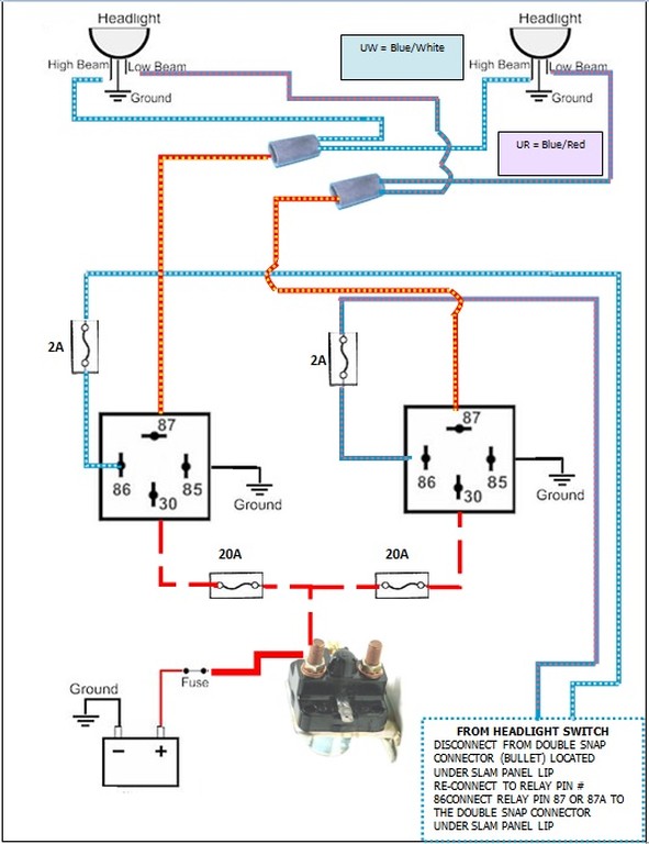
Which 'boxes', the ones with #30, 85, 86 & 87?
Those are relays; effectively a 'protective switch' that allows a 'switched accessory' to draw its power directly from the battery and reduce the load on the wiring harness and switches.
Even though I installed many relays on my mini several years ago, I did so not really 'understanding' what was happening. Now, it's exciting.
What I've learned:
When you flip the switch, the wire connected to #86 (fx. the old purple/black horn wire from the horn switch that's connected to the horn device) serves as a 'trigger' that causes an electro-magnetic field to be created along the coil inside the relay between pin #86 and the ground pin #85.
This pulls the #87 contact inside the relay from its 'normally open' state into contact with the heavy lead (#30) that's connected to the starter solenoid (battery +).
By doing this, the switch that controls the device (fx. the horn) no longer receives the full current flow used in operating the horn; the horn switch only receives enough current to activate the relay. Once the horn is no longer used, the electro-magnetic field inside the relay decays and the contact #87 springs away from #30 and breaks the circuit to the horn.
Hope this helps -
The peasants are revolting... ![]()
"Gone with the Wind" - a brief yet moving vignette concerning lactose intolerance
|
|
Total posts: 1716
Last post: Oct 18, 2020 Member since:Oct 18, 2011
|
Cars in Garage: 0
Photos: 0 WorkBench Posts: 0 |
Good thought... I shall have to inspect the 3 terminal switches more carefully. I do have some illuminated switches but these have coloured plastic "handles" (or whatever you call the bit you poke with your finger![]() . The 3 tab switch in question has a black plastic handle that doesn't look like it illuminates.... I'll let you know..
. The 3 tab switch in question has a black plastic handle that doesn't look like it illuminates.... I'll let you know..
But what about the boxes on your diagram??
Cheers, Ian
|
|
Total posts: 7075
Last post: Nov 5, 2019 Member since:Apr 25, 2000
|
Cars in Garage: 0
Photos: 0 WorkBench Posts: 0 |
|
This must be one of teh most intersting adn useful threads we've had for a long time....
However, I was also wondering what the little boxes (that Mike referred to) are??? (bottom of diagram with earth wires coming out)
Also, I was rummaging through my electrical bits and pieces last night and came across several types of "on/off" switches. Some have two connections while others have three - marked "+", "acc" and "ground". I can see how you would use each type ...but my question is "Why???". Do the three and two terminal switches have different intended purposes?
BTW, if you're worried about the complications involved with wiring in fuses with your relays, you can buy relays with inbuilt fuses - the ones I use have modern blade fuses incorporated.
Cheers, Ian
I'll venture to guess that those switches have a small built-in lamp that illuminates when the appliance is activated. The '+' is the input from the battery/power supply, the 'acc' is the terminal that you'd attach the appliance (typically a red or white wire, the appliance would also have it's own black wire (ground), and the ground is the ground (chassis (-) wire that provides the ground connection for the little lamp inside the switch.
Other simple on-off switches like the one I'm using on the 'electrical question thread' have 2 sets of 2 terminals (known as dual-pole, single position switches) which allow for the same on-off function but for 2 different appliances on the same switch. They can also be illuminated switches if you wanted to buy them... I haven't.
The peasants are revolting... ![]()
"Gone with the Wind" - a brief yet moving vignette concerning lactose intolerance
|
|
Total posts: 1716
Last post: Oct 18, 2020 Member since:Oct 18, 2011
|
Cars in Garage: 0
Photos: 0 WorkBench Posts: 0 |
This must be one of teh most intersting adn useful threads we've had for a long time....
However, I was also wondering what the little boxes (that Mike referred to) are??? (bottom of diagram with earth wires coming out)
Also, I was rummaging through my electrical bits and pieces last night and came across several types of "on/off" switches. Some have two connections while others have three - marked "+", "acc" and "ground". I can see how you would use each type ...but my question is "Why???". Do the three and two terminal switches have different intended purposes?
BTW, if you're worried about the complications involved with wiring in fuses with your relays, you can buy relays with inbuilt fuses - the ones I use have modern blade fuses incorporated.
Cheers, Ian


