The third stroke, that following the compression stroke, of our four stroke Mini engine is the only one producing power. The other three consume it. Here we’re looking at with exhaust manifolds, so what we need to consider is how to minimise power consumed on the exhaust stroke as the piston pushes the spent gases out. A free-flowing set up’s the name of the game - size playing an important role. It’s always assumed a bigger bore pipe will flow better than a small one, so there’s a tendency to follow the ‘biggest is best’ principle and go for the biggest that can feasibly be fitted. Unfortunately it simply doesn’t work, as this generalised and simple view doesn’t consider the phenomena taking place within an exhaust system.
To maximise exhaust ‘flow’, gas speed (inertia) must be kept at an optimum level. Exhaust gas going from one pipe size to a bigger one will slow down - the bigger the jump in size, the more rapidly it’ll slow. This causes two problems.
Firstly - if the speed’s allowed to slow, inertia will be lost, and any extraction effect along with it. This is the phenomena where high-speed exhaust gas can be used to clear the combustion chamber fully, ready for the fresh in-coming charge - effectively ‘pulling’ any last combustion residue out even after the piston has reached top dead centre (almost at a standstill). Loss of speed by using too big a pipe will therefore leave some spent gases in the chamber, diluting the next charge, causing a reduction in power output.
Secondly - and perhaps more importantly an overly large pipe size will cause such a reduction in gas speed, it’ll stop and actually reverse 'flow' at the end of the exhaust stroke. Bad news, as this’ll allow those horrid spent gases to flow back into the chamber - repeat dilution scenario above! So it’s important to get the lengths right. If too short, one slug of gas exiting one exhaust port could run slap bang into the end of another. Worse, the second slug could well be going in the other direction. Getting the initial (primary) pipes the right length to a well shaped junction will all but eliminate this.
Then we have the shock wave phenomena - affected by pipe length and engine speed. On the exhaust stroke, the piston shoves a slug of gas out past the valve, creating a positive pressure pulse that careens down the system at some 1300-1500 feet per second. The instant it pops out the end, a reflection’s created sending a negative pressure pulse back up the pipe towards the exhaust valve. Now, getting this back whilst the exhaust valve’s still open a-ways during the overlap period (when both inlet and exhaust valves are open at the same time when the piston reaches and stays around top dead centre for a short period) the negative pressure will help draw out them nasty ol’ burnt gases. From this we can see that to make best use of the returning negative pressure pulse for a given engine build/cam type, pipe length needs to be optimised to work at a certain engine speed.
Inertia effects can be used to good effect over a fairly broad spectrum of engine rpm. Shock wave effects, however, are only effective over a fairly narrow rev range - around 3-400 rpm. Bearing all this in mind, you can now consider what's available for the A-series.
Standard equipment.
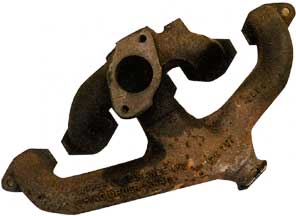
The most common standard Mini manifold is the cast iron, very short 3 into 1 type cast as one piece with the inlet manifold. It actually isn’t at all bad as far as performance on a standard engine goes. The standard, very short period cam isn’t sensitive to tuned lengths within the rpm limits it’s designed to work in, and the bore size is about right to maintain inertia at said same expected rpm limits. Consequently, changing it for a ‘performance’ manifold does very little to improve performance - except perhaps at the very top end of the rpm range, and why changing the exhaust system first pays biggest dividends. On the other hand, changing it doesn’t cause any losses - providing you don’t go over-board with the size!
The main reason for changing it is because it’s attached to the inlet manifold. Changing the inlet manifold for one of the hi-flow alloy types usually entails changing the exhaust manifold at the same time - largely because separating the exhaust manifold section from the inlet entails much sawing and grinding/filing! And as you’re already fitting/fitted a decent system, you may as well fit a performance manifold and save a load of grief. Just as likely you’re fitting a whole stage one kit anyway...it’s far easier for the customers if a decent manifold’s supplied than a new pipe section and a pack of hack saw blades! Its only real saving grace is that it absorbs exhaust resonance far better than tubular steel of any sort - so is quieter in operation.
If there’s a choice, a small-bore LCB is the best alternative. Made specifically for small-bore engines, it gives optimum performance gains - especially at higher rpm levels. Failing that - the Maniflow Cooper Freeflow works very well. Next up would be the old Cooper & S 3 into 1 type - but rare as hens teeth now.
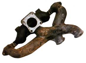 Alternatively, if you want the extra performance an LCB can give, but want the noise damping effect the cast iron manifold gives, get your hands on one of the cast LCB-type manifolds as fitted to the Metro (the MG Metro’s one is separate from the inlet - saves the sawing/grinding ordeal). With a pair of replacement tubular down-pipes fitted performance will be just as good as a tubular LCB on all but the more heavily modified engines expected to give 86-87bhp or more.
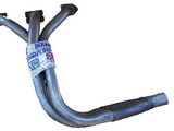
Fabricated tubular steel manifolds.
Oddly the designs and pipe sizes have been pretty much optimised for the multitude of power specifications most commonly encountered by our venerable A-series engines. Pipe sizes and lengths vary, but are distilled down into three bore size categories - ‘small’, ‘medium’ and ‘large’ - and essentially two manifold designs - ‘3-into-1’ and ‘LCB’. enough, when quizzed on the reasons behind their choice of a particular type of exhaust manifold, some folk merely say ‘coz it looks good’. You have to agree that a carefully formed tubular manifold is a great improvement aesthetically over the standard cast iron lump. Most of us are doing it in the quest for improved performance, so function must precede form as the initial thought. Over the years
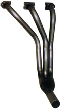
3-into-1 types:
Strangely, the least recognised yet most used if only because of ‘OE’ fitment. The standard iron manifold is a 3 into 1 - albeit very short in the primary pipes, and the first (and abundantly fitted) type. It’s pro’s and con’s already detailed above.
The next example was first fitted to the 997 Cooper, then all Cooper and ‘S’ variants until their demise. Originally cast, then later made from tube by aftermarket suppliers, this was a half-way house design between the standard cast manifold and the more commonly recognised ‘race’ 3-into-1. Longer primary pipes and larger bore size allowed higher rpm to be achieved, and ‘hotter’ cams used without detriment. It works particularly well on the small-bore engines, and big-bore units where mild cams are used, but is very rare now.
The Cooper Freeflow by Maniflow was originally developed by company owner Dave Dorrington during his time at Downton Engineering for the 970 S, and initially for the 1275 racers too. The design gives better performance than the standard Cooper item and fits small-bore engines easily. The original Cooper design hit the mechanical fuel pump, so an electric one had to be fitted - more cost and hassle. It gives superb performance on practically all road-going small-bore engines, and better performance on mildly tuned big-bore engines than the commonly used LCB. One of it’s biggest design assets is it’s easier to get a good gas-tight seal where it joins the system by virtue of the fact there’s only one simple joint to deal with.
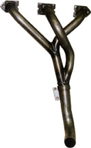
‘Race’ style 3-into-1s. No prizes for guessing the origin of it’s name! The design was translated to the 3-exhaust port A-series head from the more common 4-exhaust port race engines. Three long primary pipes optimise gas flow by having un-hindered passage to the system. The length’s necessary to allow race grind cams with long durations and overlaps to achieve maximum rpm/hp potential. This manifold is often misconstrued as being solely for absolute, fire-breathing race motors - largely because certain phenomena are either ignored or simply not known. Perhaps the most significant one concerns the right ‘tuned length’.Most believe that to maximise power, all cylinders should be ‘tuned’ to give exactly the same power, even if this means a very narrow power band. The primary pipes would be made all the same length. We already know that as far as shock-wave tuning goes, this will only benefit over a 3-400rpm range. By virtue of the space a 3-into-1 in a Mini has to fit the three primaries are all slightly different lengths. Extensive testing
 has shown such a manifold produces better over-all results than the more commonly used LCB - better bottom-end torque and power, and when correctly sized, better over-all economy. This suggests the three different pipe lengths are optimising separate cylinder power outputs at different rpm ranges - combining to give a superior useable power spread.
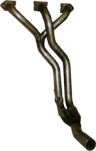
The LCB.
Labeled such because of its ‘long centre branch’. Contrary to popular opinion, the LCB’s main assets lay at the top-end of the rpm range - rarely used on any road-going Mini. The presumed better mid-range performance just isn’t there, maybe because of the more equally matched primary/secondary pipe lengths. Its popularity is almost legendary - caused by almost universal fitment as a replacement by the masses. Perhaps because ‘budget’ versions are easier to ‘cobble up’ than the others.
Conclusion
All is not what it seems. The most popular isn’t necessarily the best. Size is everything, before buying examine the relevant table carefully, and remember my motto - ‘tuning is a balance between what’s possible and what’s necessary’. Shape’s also a consideration - poor fabrication reduces effectiveness.
EXHAUST MANIFOLD SIZE SELECTION
| Manifold type | Primary end pipe size (ID) and length | Secondary pipe size (ID) and length | Centre pipe size (ID) and length | Tail piece (collector) end size (ID) | Usage |
| Cooper Freeflow | 1.250" x 11.5" | 1.375" x 15.5" | 1.250" x 16" | 1.625" | 1 |
| LCB Small bore | 1.125" x 11" | 1.250" x 15.5" | 1.250" x 25" | 1.750" | 2 |
| LCB Medium bore | 1.25" x 11" | 1.375" x 15.5" | 1.375" x 25" | 1.750" | 3 |
| LCB Large bore | 1.375"x11' | 1.50" x 15.5" | 1.50" x 25" | 1.875" | 4 |
| 3 into 1 small bore | 1.125" x 27" & 25"? | n/a | 1.250" x 26" | 1.625" | 5 |
| 3 into 1 Med. bore | 1.250" x 27" & 25"? | n/a | 1.375" x 26" | 1.750" | 6 |
| 3 into 1 Lrg bore | 1.375' x 27" & 25" | n/a | 1.50" x 26" | 1.875" | 7 |
Note: these are general guidelines based on years of development work and general usage. It’s not the be-all, end-all listing - especially where race engines are concerned. There’s nothing like careful development to get the best!!
1. The best all rounder for all road cars where up to 85-ish bhp’s expected. Only slightly restrictive up to 90 bhp. Mid range/drive-ability benefits usually out-weigh slight loss at top- end. Supplied in the better, properly developed stage one kits for most engine sizes.
2. Recommended for all small-bore engines where up to 60-ish bhp’s expected. Generally gives superior results to anything else, but isn’t commonly used.
3. Engines where 70-110 bhp’s expected. Best used on longer stroke type engines like 1100 and 1275cc units. Gives good over-all performance on race 1000s. Contrary to popular opinion, isn’t best suited to engines where less than 70 bhp’s expected - in fact can be detrimental to power, consequently not recommended.
4. Engines where in excess of 100 bhp’s expected as a minimum. Drive-ability will suffer on lower engine output, it’s really for race use or insanely powered road cars (i.e. with race spec engines giving massive power output). Absolute peak power improvements on small-bore race engines only. Better suited to 1275cc+ -based units.
5. Designed for where economy’s ultimate goal. Works quite well on race small-bore engines with 300 degree-plus cam timing where mid range needs to be maximised. Only 3 into 1 that can be suitably sealed up for road use.
6. Race engines, generally up to 1275 (up to +0.060”) irrespective of cam type. Effective on small-bore based units with cam timing in excess of 300 degrees to optimise all round performance and 1400cc+ units with cams having less than 300 degrees of timing.
7. Biggest capacity, fire-breathing race engines.
Terminology-
LCB -Long centre Branch