
| Orig. Posting Date | User Name | Edit Date |
| Jan 25, 2015 12:43PM | jeg | |
| Jan 25, 2015 09:24AM | mur | |
| Jan 25, 2015 03:35AM | jeg | Edited: Jan 25, 2015 12:39PM |
| Jan 24, 2015 11:35PM | DS1980 | Edited: Jan 26, 2015 03:48AM |
| Jan 24, 2015 11:12PM | mur | |
| Jan 24, 2015 09:52PM | DS1980 | Edited: Jan 24, 2015 10:08PM |
| Jan 24, 2015 09:32PM | mur | |
| Jan 24, 2015 07:07PM | DS1980 | Edited: Jan 24, 2015 08:04PM |
| Jan 24, 2015 11:20AM | mur | |
| Jan 24, 2015 06:23AM | DS1980 | Edited: Jan 24, 2015 06:39AM |
| Jan 24, 2015 05:36AM | jeg | Edited: Jan 24, 2015 05:39AM |
| Jan 24, 2015 05:21AM | Dan Moffet | |
| Jan 24, 2015 05:15AM | jeg | |
| Jan 24, 2015 04:15AM | DS1980 | |
| Jan 24, 2015 02:42AM | jeg | Edited: Jan 24, 2015 03:50AM |
| Jan 23, 2015 11:22PM | DS1980 | |
| Jan 23, 2015 11:17PM | jeg | |
| Jan 23, 2015 10:27PM | DS1980 | |
| Jan 23, 2015 10:10PM | mur | |
| Jan 23, 2015 09:27PM | DS1980 | Edited: Jan 23, 2015 09:33PM |

|
Total posts: 7075
Last post: Nov 5, 2019 Member since:Apr 25, 2000
|
Cars in Garage: 0
Photos: 0 WorkBench Posts: 0 |
|
Thanks for pointing it out; of course, on my 'real' mini I've got the power to the relay coming off the proper solenoid post. Details are important, so I've updated the image posted above and will be updating the car very soon.
I hope that these threads and images can be used by others; I've enjoyed the process of making them; it reinforces the learning process.
 The peasants are revolting...
 ![]()
"Gone with the Wind" - a brief yet moving vignette concerning lactose intolerance
|
|
Total posts: 5840
Last post: Nov 1, 2019 Member since:Nov 12, 1999
|
Cars in Garage: 0
Photos: 0 WorkBench Posts: 0 |
|
Awesome work. Now to go after the fine details:
both recent diagrams show power being taken from the starter side of the solenoid. I doubt in real life you would make that error, but since every detail matters, move the red line over to the other post, in case someone sees the diagram and makes a mistake.
You can and should use a very light fuse for the trigger line. 15 amps is too big. Remember that it takes hardly any power to activate. 2 amps would be fine.
|
|
Total posts: 7075
Last post: Nov 5, 2019 Member since:Apr 25, 2000
|
Cars in Garage: 0
Photos: 0 WorkBench Posts: 0 |
|
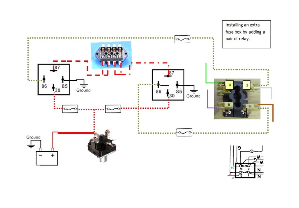
The relay allows you to have a bunch of power flow to the new components and NONE of the power goes via the original wiring harness.
...
jeg-could you make a new diagram for a fuse box with only one relay? I don't see why you have a second relay triggered by the brown wires, as they are hot all of the time. Doesn't that drain the battery?
I don't have a mini at home right now or I would go out and fit a relay and aux fuse panel and take photos for you.
If you really want to have fun, go to the web site for the Japanese Mini repair shop alecminico.jp and use google translate to read his description of why a mini needs headlamp relays.
Thank you mur, This is what I want to revisit when I get back in there. I don't think it's necessary. I'm learning a lot since I added it, thank you!
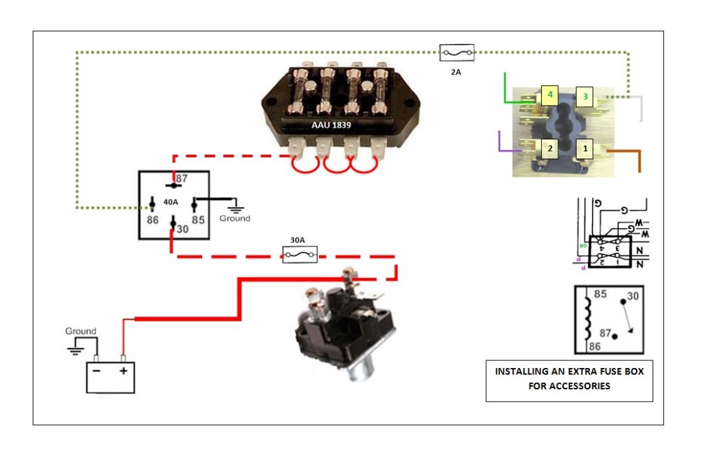
Edit: Here's the cleaned-up version of adding the extra fuse box.
The peasants are revolting... ![]()
"Gone with the Wind" - a brief yet moving vignette concerning lactose intolerance
|
|
Total posts: 188
Last post: Dec 8, 2016 Member since:Mar 5, 2011
|
Cars in Garage: 0
Photos: 0 WorkBench Posts: 0 |
|
Ah, so it's the demand of the unit that controls the current flow. So my 8-9 amp unit will only draw that much through the relay. Would you use a 10 amp relay, or go with the 30 amp? I will be using a 10 amp fuse from the solenoid to the relay. Should I use a smaller fuse between fuse box terminal 3 and #86? I saw online that when taking the resistance of the relay coil into account, the amperage across #85 and#86 is about .16 amps when working with 12 voilts.
Also, I need a SPST relay correct? or will a SPDT relay work as well.
|
|
Total posts: 5840
Last post: Nov 1, 2019 Member since:Nov 12, 1999
|
Cars in Garage: 0
Photos: 0 WorkBench Posts: 0 |
|
Everything in the car is subject to the full power of the battery. A headlamp can only draw 5 amps, times 12Volts = 60 watts. A wire that wears through its insulation on a sharp corner will short out and that will be 40 or 50 amps, but then only as long as it takes for the wire to get really hot and melt, or change shape and move because of the insulation melting and burning off.
in your home, you can plug a phone charger into the same wall plug that will serve a100 watt light bulb or an 1800 watt heat gun.
#30 on a relay is simply a connector that, when the relay is triggered, is switched to connect to pole #87b
electricity takes the path of least resistance, so a marker lamp only draws a fraction of power, a headlamp more, a cooling fan a bunch, but they get power from the same source.
|
|
Total posts: 188
Last post: Dec 8, 2016 Member since:Mar 5, 2011
|
Cars in Garage: 0
Photos: 0 WorkBench Posts: 0 |
|
Perfect, got it. I can say I have learned a thing or two, and it is appreciated.
I am still not sure how once #30 is opened, the full power of the battery is not unleashed on the relay and melt it. Wouldn't it be subjected to the full cranking amps of the battery?
Also, this circuit will be powering a homemade heat exchanger unit I will be using as Air Conditioning requiring a max of 8 or 9 amps. Should I use a 30 amp relay or go for something smaller? Again, I still don't understand how to the relay won't melt once #30 is open.
Thanks jeg, Dan, 1963, Cupcake and mur.
|
|
Total posts: 5840
Last post: Nov 1, 2019 Member since:Nov 12, 1999
|
Cars in Garage: 0
Photos: 0 WorkBench Posts: 0 |
|
The fuse you have between #30 and the solenoid would blow if there was a failure in the solenoid. Hook the trigger to #3 on the fuse block. You have a fuse between there and #86, so there is no need to be exposed to the failures of the fuse between the white wires and the green wires, or expose the relay to a potential failure that would blow their fuse.
when the ignition is turned on, everything fed by that relay gets power, and there is no additional load on the original wiring, which is what a fellow wants. You will totally do your headlamps next. A bonus of using a relay to power the headlamps is you get the greatest possible voltage and therefore brighter bulbs. You end up with nearly ten feet less length of wire from the alternator to the headlamps, so there is reduced voltage drop!
|
|
Total posts: 188
Last post: Dec 8, 2016 Member since:Mar 5, 2011
|
Cars in Garage: 0
Photos: 0 WorkBench Posts: 0 |
|
I think I'm getting this now. Been reading on relays. Let me see if I understand this:
For the relay: 86 is the command circuit that tells the relay to activate: 30 is the circuit that provides the power to the accessory: 87 is the output to the accessory. 85 is ground.
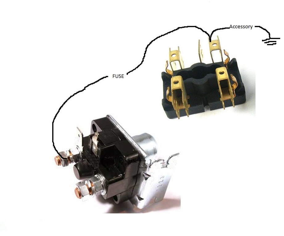
So if I wanted to install this accessory without a switch, it would look like the attached diagram. Correct? or not. What about running out of terminal 3 (switched/unfused) so this circuit isn't going through the fuse box?
Also, mur mentioned that full battery current is available at the solenoid. What keeps the relay from frying?
|
|
Total posts: 5840
Last post: Nov 1, 2019 Member since:Nov 12, 1999
|
Cars in Garage: 0
Photos: 0 WorkBench Posts: 0 |
|
The relay allows you to have a bunch of power flow to the new components and NONE of the power goes via the original wiring harness.
The only role of the solenoid for our present purpose is that it is the place where you get large amounts of power from, as it is where the main cable from the battery and the main wires from the alternator join up.
The relay is a remotely controlled switch that, using trigger wire from the car's fuse box, allows power to flow to the new circuits you might add.
You wish to put a fuse on that trigger wire so that if anything should happen, like the wire breaks or a cable wears through it, and it shorts out it does not impair the original wiring.
You wish to put a fuse on the wire from the solenoid to the relay so that if anything happens to those wires or the relay or anything downstream, the fuse blows. Keep in mind that the full power of the battery is available at that point. If you took a regular 14ga wire and hooked it to the solenoid post, and then shorted it out to the body of the car, that wire would almost instantly become red hot, melt the insulation, and light anything near it on fire till the wire completely failed.
If you use google you can easily find many great explanations of why relays are used.
jeg-could you make a new diagram for a fuse box with only one relay? I don't see why you have a second relay triggered by the brown wires, as they are hot all of the time. Doesn't that drain the battery?
I don't have a mini at home right now or I would go out and fit a relay and aux fuse panel and take photos for you.
If you really want to have fun, go to the web site for the Japanese Mini repair shop alecminico.jp and use google translate to read his description of why a mini needs headlamp relays.
|
|
Total posts: 188
Last post: Dec 8, 2016 Member since:Mar 5, 2011
|
Cars in Garage: 0
Photos: 0 WorkBench Posts: 0 |
|
You've already got the heavy battery cable to the solenoid; I only put it on there for completeness.
OK, so where would I attach my fuse? Between the solenoid and the relay?
Also, it is possible to leave the switch out, since we are attaching to terminal 4, which is the switched terminal?
|
|
Total posts: 7075
Last post: Nov 5, 2019 Member since:Apr 25, 2000
|
Cars in Garage: 0
Photos: 0 WorkBench Posts: 0 |
|
This is similar to what I did when I installed the 2nd fuse box. Of course, it's different because I started out with the 4-fuse box. I had run out of terminals, so it was time to add more.
The peasants are revolting... ![]()
"Gone with the Wind" - a brief yet moving vignette concerning lactose intolerance
|
|
Total posts: 9545
Last post: Apr 25, 2024 Member since:Aug 14, 2002
|
Cars in Garage: 0
Photos: 0 WorkBench Posts: 0 |
|
Oh, I was looking at the wrong terminals.
I'm clear on everythinig except why would a wire run from the battery to the solenoid? In't the solenoid the power source?
Thanks for the effort! Much appreciated!
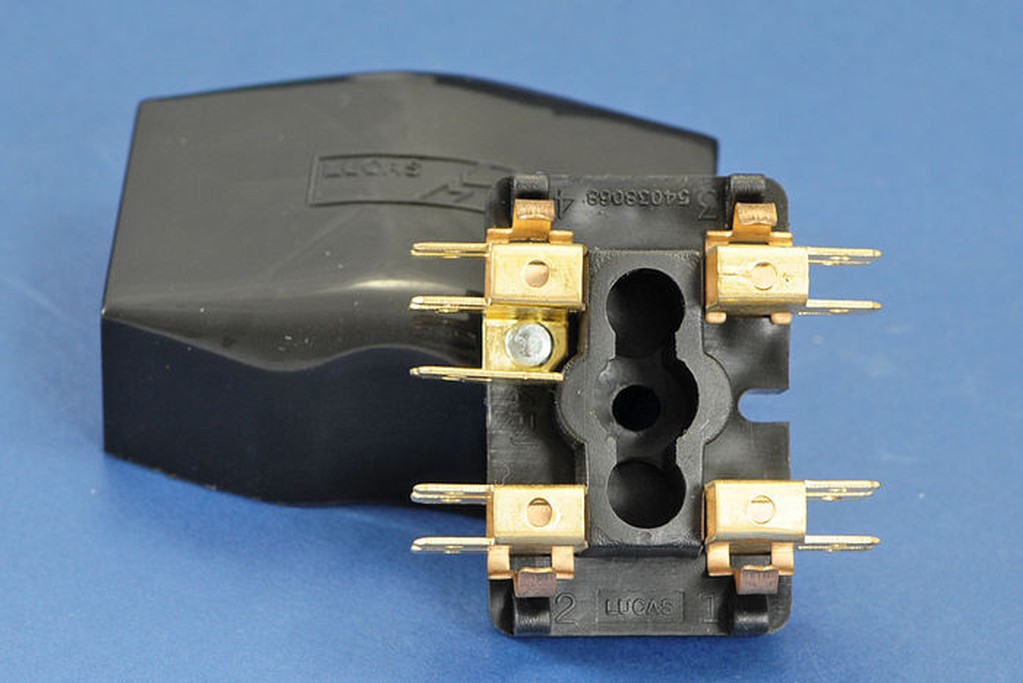
The battery IS the source of power. The very large battery cable runs from the battery under the car to a very large terminal on the solenoid. This terminal serves as the main distribution point for all electricals. The large terminal has brown wwires connected to it to lead off in various circuit directions. Brown signifies unfused, always powered wires. The other large terminal on the solenoid is connected to a large short wire feeding the starter motor. The two big wires are to carry the huge current needed to turn the starter. This curent is too big for a typical switch so a jumper bar (or plate) inside the solenoid is used to link the two big terminals when you want to crank the engine. The bar is spring loaded and uses an electro-magnet coil to close the contacts. So the solenoid is more properly described as a "solenoid switch". The electromagnetic coil is powered through a small white/red trace wire coming from the igntion switch to one of the small terminals. (Your particular solenoid might only have three terminals.)
On later cars with a ballasted ignition the soilenoid provides a secondary temporary switch service when you turn the key to 'start' - it provides 12V to the coil via a white/yellow trace wire. This provides a spark "boost" during cranking (when avvailable voltage drops) because ballasted ignition coils normally function on about 8 to 9 volts.
Typically eveerything is eventually grounded to the body shell, so the other battery cable is very short and connected to the boot floor right at the battery. Most cars are "negative" ground, meaning everything in it is wired to have the negative battery terminal connected to the ground wire. Older cars were built "positive ground", with everything configured to suit. To complicate matters, some 'positive' cars have been converted to 'negative' to allow easier connection of later accessories like stereos, which only work 'negative ground'.
Be careful with batteries and the big cables and teminals - there is enough juice there with which to do a bit of welding. My wife once was changing spark plugs (not in a Mini) and the back tip of the wrench she was holding accidntally touched the solenoid's battery terminal, instantly heating up a 3/8" breaker bar, short extension and a spark plug socket too hot to hold. (She did learn the first time!) That is why solenoids are typically situated in the engine bay well away from other equipment - to avoid accidental shorts. On later cars they are mounted on the starter.
.
"Hang on a minute lads....I've got a great idea."
|
|
Total posts: 7075
Last post: Nov 5, 2019 Member since:Apr 25, 2000
|
Cars in Garage: 0
Photos: 0 WorkBench Posts: 0 |
|
You've already got the heavy battery cable to the solenoid; I only put it on there for completeness.
The peasants are revolting... ![]()
"Gone with the Wind" - a brief yet moving vignette concerning lactose intolerance
|
|
Total posts: 188
Last post: Dec 8, 2016 Member since:Mar 5, 2011
|
Cars in Garage: 0
Photos: 0 WorkBench Posts: 0 |
|
Oh, I was looking at the wrong terminals.
I'm clear on everythinig except why would a wire run from the battery to the solenoid? In't the solenoid the power source?
Thanks for the effort! Much appreciated!
|
|
Total posts: 7075
Last post: Nov 5, 2019 Member since:Apr 25, 2000
|
Cars in Garage: 0
Photos: 0 WorkBench Posts: 0 |
|
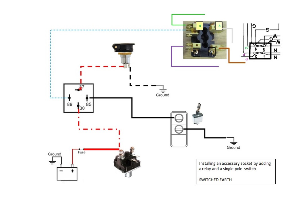
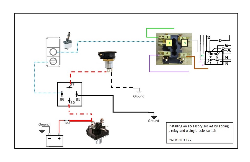
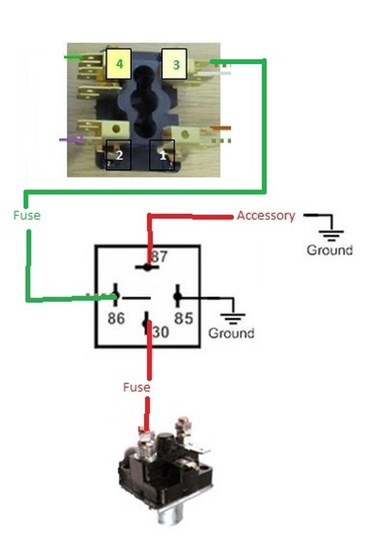
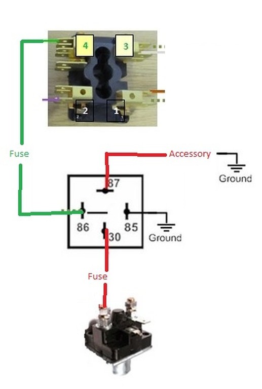
I hope this is right - as recommended by mur, version 1 is switching ground. Version 2 is the more common switching the positive. There are small numbers beside the fuses which indicate which terminal is which.
I think it best that someone double check these...
The peasants are revolting... ![]()
"Gone with the Wind" - a brief yet moving vignette concerning lactose intolerance
|
|
Total posts: 188
Last post: Dec 8, 2016 Member since:Mar 5, 2011
|
Cars in Garage: 0
Photos: 0 WorkBench Posts: 0 |
|
Thanks jeg! Apparently I need pretty pictures and colors to figure this out. I don't know why I'm not getting it.
|
|
Total posts: 7075
Last post: Nov 5, 2019 Member since:Apr 25, 2000
|
Cars in Garage: 0
Photos: 0 WorkBench Posts: 0 |
|
I'll try to do a drawing; heck, I've been practicing.
I have also learned quite a bit by doing these drawings and listening to the feedback and instruction given, so now I'll need to re-visit my 2nd fuse box and make sure that I've got it wired properly. For example, I've not installed a fuse between the ignition switched accessory lead and the relay. I do have fuses between the starter solenoid B+ post and the relays, though.
The peasants are revolting... ![]()
"Gone with the Wind" - a brief yet moving vignette concerning lactose intolerance
|
|
Total posts: 188
Last post: Dec 8, 2016 Member since:Mar 5, 2011
|
Cars in Garage: 0
Photos: 0 WorkBench Posts: 0 |
|
OK, so the wiring would originate from the 12v supply from the solenoid, but would always be powered. How would I tie it in so that it is being triggered from the ignition circuit?
|
|
Total posts: 5840
Last post: Nov 1, 2019 Member since:Nov 12, 1999
|
Cars in Garage: 0
Photos: 0 WorkBench Posts: 0 |
|
To give you an idea of amperage, an H4 headlamp bulb draws about 5 amps at 55 watts. My Cooper S, with a generator, running at night with the heater fan, ignition fuel pump and halogen headlamps would discharge the battery and I would need to push start it at gas stops!
The starter solenoid is akin to a giant relay for the sort of current that a starter motor draws. The one post on the solenoid is the cable to the starter while the other is the main +12V for the car. The big cable comes up from the battery, and the main cables from the alternator come back to this point. They are always powered when the battery is connected.
A relay would allow considerable loads to be routed to the various fans, inverters, cigar lighter outlets and so on straight from this main +12V power point. Triggering it from the ignition circuit will allow it to turn on and off with the rest of the car, but no load is drawn through the original wires.
|
|
Total posts: 188
Last post: Dec 8, 2016 Member since:Mar 5, 2011
|
Cars in Garage: 0
Photos: 0 WorkBench Posts: 0 |
|
OK, I guess I have no idea how to do this. I was just going to run from terminal 4, through an inline fuse, to the accessory plug. I see how this will add current through terminal 4, but I guess I don't see how it will strain the system if I keep everything under 30 amps.
I want it to be switched by the ignition. Is the starter solonoid activated by the ignition switch or is it always on? If it's switched, can I just wire from the starter solenoid rather than terminal 4?


