
| Orig. Posting Date | User Name | Edit Date |
| Jan 14, 2015 07:38PM | jeg | |
| Jan 14, 2015 07:28PM | MtyMous | |
| Jan 14, 2015 07:07PM | jeg | |
| Jan 14, 2015 06:49PM | MtyMous | |
| Jan 14, 2015 06:49PM | minimans | |
| Jan 14, 2015 06:23PM | jeg | Edited: Jan 14, 2015 07:15PM |

|
Total posts: 7075
Last post: Nov 5, 2019 Member since:Apr 25, 2000
|
Cars in Garage: 0
Photos: 0 WorkBench Posts: 0 |
|
The rear fog lamp (red) will turn on together with the new front fog lamps; the red dash indicator also.
 The peasants are revolting...
 ![]()
"Gone with the Wind" - a brief yet moving vignette concerning lactose intolerance
|
|
Total posts: 2277
Last post: Oct 6, 2022 Member since:Nov 18, 2007
|
Cars in Garage: 0
Photos: 77 WorkBench Posts: 2 |
|
Sure. You can absolutely run them through one switch. In fact, you can run multiple relays off one switched source as the amp draw to open a relay circuit is relatively tiny. Most automotive relays are typically 150-200mA for a typical automotive relay. They generally have around 85 ohm coils.
But I'm still sort of confused. Was the description I gave accurate to what you're trying to do? It sort of sounds like one of the switch positions is already used for the rear for light. If that is the case, and yu're trying to isolate both sets of foglights (2 different trigger sources) and run through the samer terminal on a switch then no, you can't really run it that way. But before I make that my final answer Regis.. Can you sort of explain a little better what paths you want to take? Refer to my first post.
|
|
Total posts: 7075
Last post: Nov 5, 2019 Member since:Apr 25, 2000
|
Cars in Garage: 0
Photos: 0 WorkBench Posts: 0 |
|
Sorry for the A&W mis-types, it can get a bit confusing - I'll edit shortly.
My initial thought (haven't put pen to paper yet, just waiting for parts that I ordered only tonight and doing the mental installation right now), was that the one switch could serve both fogs and driving lights, and that one relay could function for both pairs of lamps. The truth is, both lamp kits come with relays and switches (rocker-type [I really don't like them, prefer toggles]), so it's not the end of the world if I need to use both, but since I'm running out of physical space, thought that I could try to better maximise capacities. The idea of the using this on-off-on switch is that right now, only ½ is being utilized, and at around a hundred bucks each, I'd rather not invest in another on-off type.
Or two, for that matter, I'd still have ½ of this one unused...
If I were to use 2 relays, it would probably need a separate switch for each pair of lamps since there's only 3 terminals.
The peasants are revolting... ![]()
"Gone with the Wind" - a brief yet moving vignette concerning lactose intolerance
|
|
Total posts: 2277
Last post: Oct 6, 2022 Member since:Nov 18, 2007
|
Cars in Garage: 0
Photos: 77 WorkBench Posts: 2 |
|
Hey Jeg, I'll try to tackle this one, but i'm sort of confused what your end goal is. Here's what I took from it and tell me if I'm wrong.
You've got a 3 position switch. Position "A" is up and on. Position "B" is middle and off. Position "C" is down and on. What you're trying to do is have position "A" when on receive signal from the high beams and then feeding that signal to turn on the driving lights. Inversely, you want position "C" to be on and receiving its signal from the low beams? And in both instances of "on" you want them to illuminate the dash indicator? Is that accurate?
Also, I think you may have mistyped watts in a few places where you meant to put amps. Not a big deal if you know what you meant to type. I can tell by your info that you probably know what you meant but it just got typed wrong. No biggie. I see what you're getting at.
|
|
Total posts: 1404
Last post: Jun 21, 2018 Member since:Oct 8, 2013
|
Cars in Garage: 0
Photos: 0 WorkBench Posts: 0 |
One switch operating both relays. you then only need one switch but get the safety of one relay per pair of lamps?
Mini's are like buses they come along in a bunch
|
|
Total posts: 7075
Last post: Nov 5, 2019 Member since:Apr 25, 2000
|
Cars in Garage: 0
Photos: 0 WorkBench Posts: 0 |
|
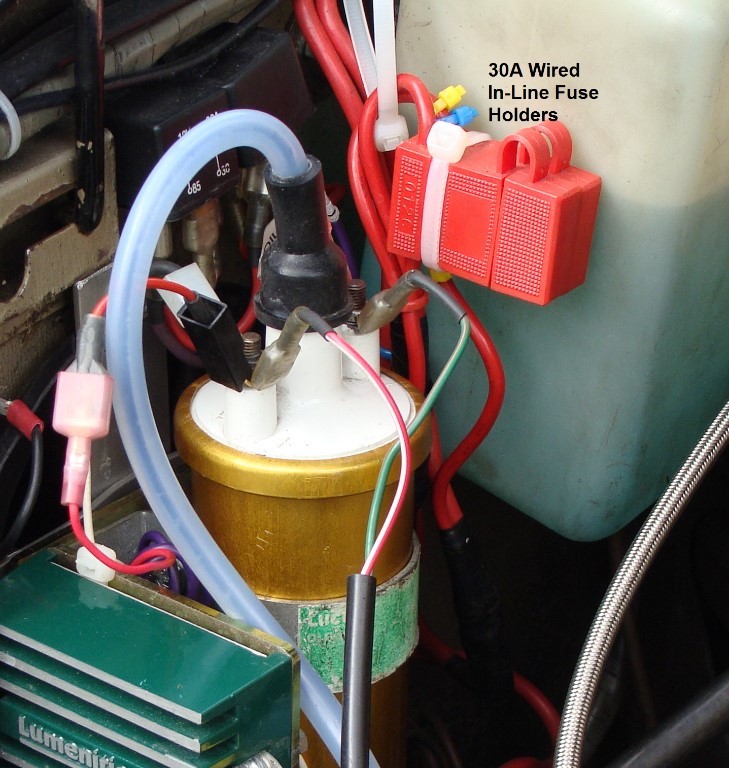
I thought it time to tart the mini up a bit, so I've just ordered a works-style lamp bar, a pair of PIAA 510 ion crystal fog lamps (55W halogen, kit 05161) and a pair of PIAA 510 smr xTreme white plus driving lamps (55W halogen, kit 05192). Along with this set of lamps and lamp bar, Vehicle Wiring Products is sending 20 meters (each) of 2mm sq. 28/0.30 (color UR and UW) 25 amp wire to connect from the battery (+) to the relay(s) and a pair of 30A wired inline fuse holders similar to those in the 2nd photo.
I wouldn't mind some qualified brain-storming, as I find this a bit complicated.
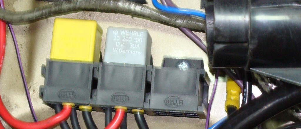
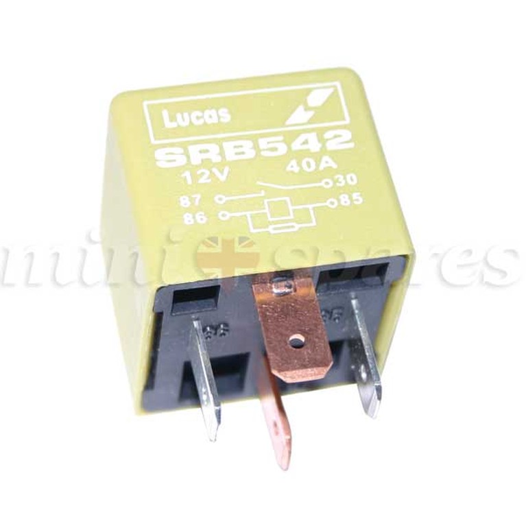
As you can see in the attached fuzzy photo, there's an empty relay socket. The 'yellow-colored' relay in the photo is rated at 40A, and I've another one on the way from MSC.
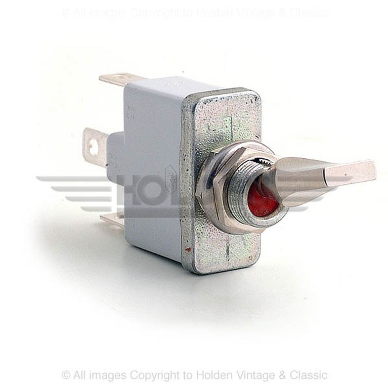
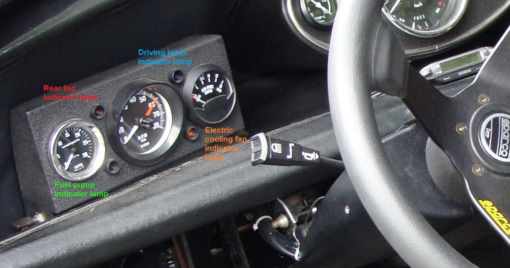
The switch I plan to use is the on-off-on (APEM 020.153 , 3 terminals, rated at 35A), as I've got one already serving the rear-mounted red fog lamp as well as the dash-mounted fog-lamp indicator lamp. There is a 6-terminal switch available (APEM 020.154) which would remove the necessity for piggy-back connectors, but I'm still on the fence on this. Unless I'm wrong, using the 3-terminal switch could work but would require 2 piggy-backs on the 'out' terminals; one to each set of aux. lamps and one to the red dash-mounted indicator lamp, seen in the 4th picture. In turn, the red dash-mounted indicator lamp would require a piggy-back connector in order to illuminate when either the 'on' or 'on' is switching either the driving or fog lamps. The terminal used for the fog lamps would also need to serve the rear-mounted red fog lamp which carries a 21W halogen bulb (010.452).
So, the total current draw for the combined fog lamps is 11A + the small 5W dash indicator, so at 11½A, we can call it 12A. The driving lamps come in at 9½A, so we can call it 10A to be on the cusp of safe.
So, after all this typing, my thought:
Since only one pair of lamps can be operated at a time, perhaps the 40A relay and the single 35A switch could be used for both sets of lamps.
I'm wondering if using a 'Y' wire from relay pin 86 could get it's connection from the center of the on-off-on switch, with each 'on' of the switch connected to the vehicle's low or high beam (UR/UW) bullet connector and also to its red (fog) or blue (driving) dash indicator lamp.
Pin 87 to each of the pairs of lamps which is connected via bullet connector to the original high/low beam double bullet connector (will change to tripple-tube bullet connector if necessary) at the slam panel.
The ground wire for pin 85 will be the same thick ground wire that I've used elsewear, by memory I believe it's 44/.30mm 33A but I'd have to check (forgot to order 25A black), and pin 30 would get the 25A wire from the battery.
The lamps would be grounded in the usual fashion.
So.... Any thoughts? Or, should I just install the 2 factory relays and buy another switch. I really don't have so much available space for another relay; they're tucked all over the car (horn, high beams, low beams, fuel pump, electric fan, accessories (with car running), switched accessories ('acc' key position). Worst of all, where to put the extra switch???
Edited for A&W mis-types and labelling photos.
Another edit - the blue dash-mounted Driving indicator lamp is currently unused, but I'd had the foresight to purchase and install it when I installed the auxiliary gauge pod (DKLawson's old one, bought for $20 and a jar of homemade marmelade - thanks Doug!).
The peasants are revolting... ![]()
"Gone with the Wind" - a brief yet moving vignette concerning lactose intolerance


