Read all instructions thoroughly before proceeding with this installation !!!
These instructions assume that the installers are experienced in basic auto repair techniques and have at their disposal, in addition to a good quality workshop manual, a comprehensive selection of wrenches and other tools, including an electric drill and bits, round and flat files, automotive electrical terminal crimpers or soldering iron, "pop" rivet tool with rivets and a stock of other bits and pieces as commonly used in modifying or repairing cars.
The kit contains the pieces necessary to convert a Bugeye Sprite from a rear-hinged bonnet to a quick-release front-hinged configuration, allowing rapid removal for major repair and easier access for normal maintenance.
The kit does NOT contain a latching mechanism or safety catch and permanent removal of the front bumper is necessary to install the kit. Tension-type fasteners or straps such as Mini Mania P/N MS118 are recommended for securing the hood, but note that the rear of the bonnet MUST be secured by some method of your choosing. Fresh hood seals, bumpers, and buffers are also recommended.
PREPARATION AND HARDWARE INSTALLATION
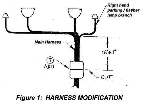
| 1. | Referring to Figure 1, peel back the protective jacket of the wiring harness to expose the individual wires, Make note of any color coding and label all wires BEFORE cutting them. Carefully cut the front lighting array wiring harness at a point just behind the right- hand turn signal/marker lamp, leaving a 16 to 17 inch pigtail. Leave yourself enough of the stump of the hood harness to easily attach electrical terminals to the individual wires. |
| 2. | Refer to your shop manual and remove the bonnet. |
| 3. | Remove the locking assembly and handle, rod clips, bonnet latch/striker plate, safety catch and locating pegs from the bonnet and save them for the next swap meet or, depending on their condition, for fishing weights. |
| 4. | Remove grille assembly. This will be reinstalled in a later step. |
PREPARATION:
| 1. | Remove the hinges from the cowl. |
| 2. | Remove the front bumper by unbolting the mounting bars from the chassis. Set these aside for the next swap meet (see #3 above). Inspect carefully the condition of the front mounting bosses - these should be free of burrs and perpendicular to the chassis extensions. Clean up the bosses and align as required. |
| 3. | Remove the bonnet and auxiliary stays from the body shell. |
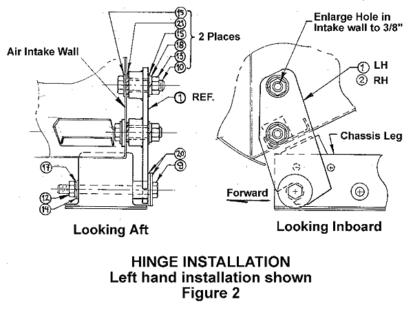
| 4. | There is a hole just above that through which the locking rod passes. Enlarge this hole to accept a 3/8" diameter bolt. See Figure 2 and test fit before enlarging the hole. |
INSTALLATION:
| 1. | Attach the 9S0025 and -26 Hinge Brackets to the cooling ducts as illustrated, using the 3/8" bolts, nuts and washers provided. For the moment, leave the bolts finger tight. |
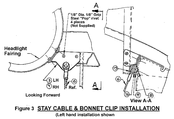
| 2. | Install the 9S0021 and -22 Clips onto the hood between the headlight fairing and the cooling air duct upper support angle, using 1/8" diameter STEEL pop rivets (not supplied) as shown in figure 3. BEFORE DRILLING, adjust (bend) the fairing leg of the clip to get a good fit between the clip and the fairing before drilling the rivet holes in the hood members. |
| 3. | When the clips have been riveted in place, bolt the lug end of a 9S0024 Stay Cable to the clip on each side, and lay the length of the cable along the side of the duct as shown in figure 3. |
| 4. | Attach a 9S0021 Stay Clip to each side of the radiator where the splash shield support brackets are attached, using the original fasteners. |
FINAL INSTALLATION AND ALIGNMENT
| 1. | Lubricate (grease) the forward bumper bosses on which the hinges will pivot and the slots in the hinge brackets with a "stick-type" or other long-lasting lubricant. |
| 2. | With the hood near the vertical and securely supported by a friend or someone else you trust, engage the slots in the hinge brackets with the bumper bosses, and carefully lower the hood until its rear edge is resting in place on the cowl. |
| 3. | Adjust the fit of the hood to the cowl as required, then fully tighten the hinge bracket securing bolts. Use drift punches or other similar devices inserted through the original locating peg holes to ease alignment. |
| 4. | Raise the hood and snap the 9S0024 Stay Cables onto the clips attached to the radiator support. |
| 5. | Install the gang connector halves to each side of the previously cut wiring harness, ensuring that all wires are correctly aligned. Connect the two halves, neatly lay the rear portion of the harness along the inner fender and secure it with suitable cable clamps or wire ties (not provided). |
| 6. | Check that all fasteners are secure. |
| 7. | Install the hood hold-down straps or locking mechanism of your choice. |
| 8. | Reinstall the grille assembly. |
SUPPLEMENTARY INFORMATION
Ignition Timing:
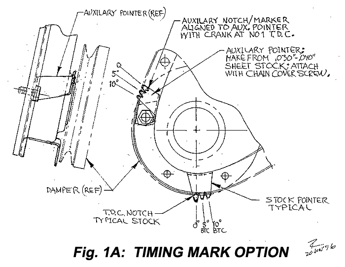
While the fitting of this kit greatly improves engine access in general, when the bonnet is raised, direct viewing of the timing marks on the crankshaft damper and timing pointer on the chain cover is no longer possible. The bonnet could be removed from the car, of course, but since this is a two-person operation, this may not always be convenient. A more practical method is to add an auxiliary timing mark and timing pointer which are more easily viewed from the topside of the engine bay.
An example of one such arrangement is illustrated in figure 1A. A pointer is not included in this kit, but could be readily fabricated.
Electrical Ground:
This kit installation provides fewer ground paths between the bonnet and the rest of the car body than the original configuration, This may result in poor headlight performance, i.e.: dimming, flickering, etc, although none of these conditions have ever appeared on our development car, even in the rain.
The straightforward solution, if poor grounding is suspected, is to provide an additional ground wire through the seventh, unused, pin of the connector used in Final Installation, step 5.
Should that not be sufficient, a wire of as heavy gauge a practical, secured to both the hood and main chassis, ought to provide the needed ground path (a braided ground cable, available in most auto parts stores in various lengths, works exceedingly well in this application).
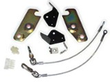
Parts List
Part No. Description Quan/Kit


9S0025 Hinge Bracket, LH 1

9S0026 Hinge Bracket, RH 1

9S0021 Bonnet Clip, cable, LH 1

9S0022 Bonnet Clip, cable, RH 1

9S0023 Clip, cable anchor 2

9S0024 Cable assy, hood stay 2

BRI827 Connector, 7-pin 1

HF0405 Bolt, 1/4-28x0.63 2

HF0530 Bolt, 5/16-24x3.5 2

HF0612 Bolt, 3/8-24x1.5 4

NP1041 Hex nut, 1/4-28 2

NP1051 Hex nut, 5/16-24 2

NP1061 Hex nut, 3/8-24 4

WS3051 SAE Washer, 5/16 2

WS4061 SAE Washer, 3/8 8

WL2041 Lockwasher, 1/4 2

WL2051 Lockwasher, 5/16 2

WL3061 Lockwasher, 3/8 4

WS3041 SAE Washer, 1/4 2

WF3521 Fender Washer, 5/16x1.25 4

WT2061 Externally toothed washer, 3/8 4