

|
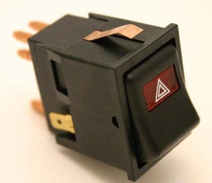
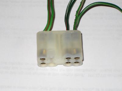
In Canada, MK III minis were imported with what was then an excellent new feature, "Hazard Lights." Sometimes called 4-way flashers, this switch allows the turn signal lamps of both left and right sides of the car to work at the same time regardless of the ignition being turned on. There is a little bit going on inside that switch to make this happen, and a failure here can lead to turn signal lamps not working. It helps to consider the Hazard Switch as selecting either "...turn signals on via the turn signal switch when ignition is on..." or "...both left and right turn signals flashing; ignition on or off." To accomplish this, the mini's wiring harness employs two flasher units, one for the regular turn signals and one for the Hazard system. The Hazards system flasher has +12V power at all times. When the Hazards switch is switched ON, power comes to the switch from the flasher and goes to both the left and right turn signal circuits. Lights blink at all four corners of the car. The second flasher is powered when the ignition is turned on. With the Hazards Switch in the OFF position AND the ignition is turned on, +12V power is routed through the Hazard Switch and on to the turn signal switch, which then can be used to select turn signals for either side of the car. Many people have a hard time tracking down problems with failed turn signals. The lights quit working and preliminary trouble shooting shows no issues, fuses appear fine. Frequently this is because of a failed Hazard Switch. Early MK III versions of this switch are robust, but can fail as the grease inside ages and hardens. These can be dismantled and cleaned successfully. Later MK III and MK IV+ onward switches are smaller and quite failure prone. They are difficult to impossible to fix. The first thing to do with either switch is to carefully remove it from the panel and use a test lamp or multimeter to check for power coming into the switch. Remember, it is fed from 2 sources: The Hazard System has a +12V wire that is powered all of the time, while at the other end of the plug there is a wire that is powered with the ignition ON. I would tell you the colours, but as I am typing this I have a Hazard Switch and its plug, along with a couple of inches of wire going into the wire harness, and the colours have been slightly changed from the wiring diagram I have beside me. I think this is because of subtle changes in harnesses over the years. Because of these subtle changes, be sure to use the wiring diagram for your specific mini. Here are photos of a well used Hazard switch and the plug it fits into:
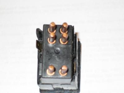
This is from a 1990 Japanese Mini's wiring harness, but it is almost exactly the same as the plug on my 1975 MK III. With the switch in the off position, there should be continuity across the two pins at the bottom of the switch. These carry the current up to the turn signal switch on the steering column. One of the light green with brown tracer wires will have power when the ignition is on. At the top of the switch, and plug, are another four pins. One is +12V coming from the Hazard Flasher, the green with white and green with red are for the left and right turn signals circuits, and that last green wire is to illuminate the Hazard Switch itself when the MK III Hazard Switch is turned on. This is a later configuration: Early versions of this switch were illuminated with the dash lights, whereas this car has the hazard switch flash along with the turn signals and the turn signal indicators when the Hazard Switch is turned on. Consider switches a wear item, just like tires or brake pads, and expect to replace them at least once during the life of the car. Since MG Midgets and Austin Healey Sprites are basically minis without roofs with the engine in the wrong way, this Hazard Switch architecture applies to them as well. |
-
 YUF101660List: $16.95Sale Price $14.92


Let's make sure we're showing you the right parts! Please Select your car type Below:


