|
Time to arrange all those agonised-over, carefully selected and applied suspension components to give of their best.
This is one of those subjects viewed as a ‘black art’, largely because of lack of understanding and confusion. The confusion part is because folk encompass the whole suspension set-up deal with suspension arrangement and design, lack of understanding instilling terror at the thought of ‘fiddling’ with the suspension components. The latter also fueled by the knowledge that expensive specialist measuring equipment is needed. Well, there is no black art – you can work the magic. More a case of a long day’s labor made easier by having an assistant. Only simple equipment is needed, and the relevant measuring equipment is available at real DIY money.
Ground level
The first – and essential - requirement is a level surface on which to work your magic. A surface with any gradient will cause the suspension to tilt in that direction, subtly affecting geometry readings in the case of mild gradient. Wildly altering it in the case of an ‘Everest’ one. I’m sure you’ve all observed the way your Mini’s suspension seems to have sunk on one side or the other (front and rear too) when parked on a gradient. That ‘sinking’ alters the significant suspension geometry angles. Whilst an absolutely flat floor is the pinnacle of surfaces to work on, the average concrete garage floor will be – through the nature of it’s construction – pretty much there.
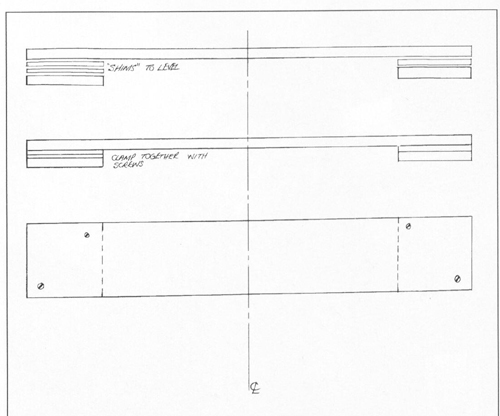
Check the selected area with a builder’s spirit level and long, straight piece of wood, metal tube, angle iron, etc. If the surface is far less flat or more graded than it appeared to the naked eye – no problem. All that’s needed are four square pads made in wood to sit under each wheel/tyre, linked by two long boards to hold them in position – one for the front and one for the rear. Set the car where desired, then draw squares around the wheel/tyre to floor contact patches with chalk Ideally, and if feasible/allowable – check with your parents first kids – paint them on for future use. Shift the car out the way, and set the pads down on the marked squares, then lay boards across these. Using a builder’s spirit level, shim the pads with thin material (‘lino’ squares are ideal for this) until the pads/boards are level side to side, front to rear, and diagonally. Take your time and get this right. Once happy, use some self-tapping wood screws to hold everything in place. Mark the boards with their corresponding ‘ends’, and the floor positions if allowed. The pads don’t need to be hi-rise affairs, so keep this set-up as low as possible – 2” thick pads are a pain to push the car up on to! Sorted – you now have a sound base to work on.
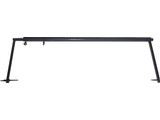
 Simple way of creating a level surface. Keep pads as low as is practical, otherwise ramps will be needed to get your Mini on ‘em! Simple way of creating a level surface. Keep pads as low as is practical, otherwise ramps will be needed to get your Mini on ‘em!
Hi-Tec tooling
One of the factors frightening most folk off dealing with their suspension – specific measuring equipment. Heightened by visions of laser/optical geometry setting systems seen in use at your local wheel/tyre fitters and a supposed degree in rocket science to operate it, or complex free-standing equipment used by various race teams observed at circuit paddocks. They use these because they can or have the budget to do so. This is over-kill for you and me. Fortunately there are some very basic alternatives that will allow surprisingly accurate measurement for minuscule investment that are as easy to use as a ruler.
The list of essential tools – except the necessary spanners/sockets to make any adjustments - goes like this:
A piece of string long enough to go completely around the car. Builder’s nylon string/plumb line string is spot-on for this.
Tracking gauge. In descriptive terms, nothing more than a large ‘G’-clamp with a scaled/measured adjustment is needed for width comparison. Easily made if suitable materials are available, or far easier bought. The cheapest, most basic example is made by Min Tec, available through Mini Spares/Mania costing around a measley $55.28. Cheap or what?
Caster/camber gauge. An instrument capable of measuring vertical angles in degrees/parts there-of. Not so easy to make – the scale being VERY difficult to compile and draw. Again there’s no need – Min Tec to the rescue once more via Mini Spares/Mania costing around $59.22.
Lastly, a pad and pen to record everything you do on. Keeping detailed records are essential when further alterations are made to fine-tune the suspension to your tastes.
Both Tool10 and Tool11 are, whilst being extremely cheap and basic are supremely easy to use, very accurate, and come with easy instructions. And that’s it. For the price of having some ham-fisted mechanic rearrange your suspension to what you ask (hopefully) you can do it a thousand times at home! Unabashed plug? Maybe, but it’s for YOUR benefit.
Line a-stern
Initially, centralise the steering rack as detailed in the jolly old workshop manual (wordage and space is at a precious premium here!), and set the front tracking to ‘straight ahead’. Set tyre pressures correctly and accurately, then get your pride and joy up on the pads ensuring the wheels are as straight ahead as possible. Push it on. Don’t jack it up then place the pads underneath. You’ll need to avoid jacking the car up where at all possible as it seriously affects the settings by disturbing your carefully set ride heights. When jacking is unavoidable, once the car’s been set down, roll it backwards and forwards several times whilst joggling up and down on the sills (doors open of course!) then leave to ‘rest’ for a couple of minutes. This will help settle the suspension down again. Having some wooden 'wedges' made to use as ramps to push the car up on to the blocks will help immensely - the longer the better.
Now to establish that all your efforts in ensuring the shell is straight and square and subframes in the right positions as detailed in previous ramblings have been successful. To do this, tie one end of your string to a suitable point level with, or near to, the wheel centre height. Go round the car, passing through the centres of each wheel, and back to the front (or rear – where-ever you decide the best anchor point is). The string needs to be touching the tyres, so if arch extensions are fitted and will prevent this, they need to be removed. If arches are permanently attached this obviously isn’t on.
 String must pass all way round car, through wheel/tyre centre-line, and be touching the tyre sidewalls. A double-check for front to rear subframe/suspension alignment. With front tracking set at straight-ahead, there should be a gap between the string and leading edge of rear tyres. No gap suggests massive toe-out – VERY dodgey. The gap should be even. Get it sorted before going further. String must pass all way round car, through wheel/tyre centre-line, and be touching the tyre sidewalls. A double-check for front to rear subframe/suspension alignment. With front tracking set at straight-ahead, there should be a gap between the string and leading edge of rear tyres. No gap suggests massive toe-out – VERY dodgey. The gap should be even. Get it sorted before going further.
What will be needed here are four blocks of wood, or some other item that will do a similar job. These blocks need to be attached to the tyres/wheels, one on each tyre/wheel arranged at wheel centre height, to the rear of the tyre/wheel at the back, and the opposite at the front. Tank/duct tape can be use to stick them on. By necessity they need to be thick enough to get the string away from the arches, and must be of near-exact size in this respect.
Check the front wheels are straight-ahead, and the string is touching both edges (front and rear) of both tyres or blocks. Now inspect/measure the leading edge of the rear tyres where the string passes. There should be a gap between the leading edge and the string. If you got the subframes/shell square the gap each side will be more or less equal. If wildly out – more than say 1/16”, you need to sort out why, and correct it – be this a bent radius arm or mis-aligned subframe. If it’s a 1/16” or less – this can be sorted when doing the tracking. Make a note of which side has what gaps, and remove the string. Having done that – it’s on with the show!
Geometry juggling
The first detail to set is the rear tracking. The reason for this is simple – adjustment in rear tracking affects rear ride height, but DOES NOT affect camber. Rear track is altered by moving the radius arm pivot shaft ends backwards or forwards. Marginally affecting ride height when using outer end track/camber adjustable brackets or fitting shims between the bracket and subframe, more seriously when camber (fixed or adjustable) only outer brackets are used. The latter because the inner end has to be moved backwards by elongating the mounting hole where toe-out exists before correction. It shouldn’t, but has been known – especially where pattern subframes and some negative camber rear brackets are used. This moves the suspension knuckle socket backwards, which raises the rear suspension height.
Set the rear tracking by either using the facility built in to the brackets you may be using, adding shims between the outer bracket and subframe to add toe-out (reduce toe-in or give toe-out) or elongating the inner pivot shaft hole in the required direction. Backwards to reduce toe-in, forwards to add toe-out where an extreme amount of toe-in is present, and not sort-able with outer shims. If elongating the hole, a filler-key will need to be produced to stop the arm moving back to its original position. Don’t forget to do the rolly-bouncy-settley thing after any jacking up. As a starting point, set them at 1/16” toe-in.
Rear camber should now be set whilst you’re at that end, and if you have adjustable brackets. Personally I can’t see the point in using static camber brackets, as these maintain any side to side differences your car started out with, and too much negative camber isn’t good. Initial setting here is ‘straight up’ – zero degrees camber.
Now set the ride height to where you want it. In the absence of any consistent and deadly accurate measurement points – use wheel centre to arch peak distance, or (what I do) is use sill edge to floor (pad level). Both providing there aren’t any obvious deviations from the standard line. Assess which will give you the most accurate readings. Folk have their own opinions on which is the best way to achieve this – personally I remove the bump stops, lower the car as far as it will go, then winch it up from there. Mainly because having tried it the other way, I found a certain amount of ‘settling/sagging’ occurred. Adjust both fronts and rears the same amount, do it in small amounts, and never keep adjusting one corner. It will seriously affect the corner weights/stability (more in another article). Raising one corner will usually also lift the diagonally opposite corner a little. Again – do it a little at a time and measure ALL FOUR corners each time. Ride height suggestions are a bone of contention. I’m going to outline the effects in another article some time; for now just don’t go too low. Lowest I would say is just off the front bump stops, and ¾” higher at the rear. Once happy with the ride height, press on.
Take a set of readings off the front for caster and camber to be your initial guidelines. Caster angles are next, adjusted by altering tie-rod length. These need to be as even as possible. If you are using fixed-camber bottom arms, as long as the readings are within half a degree with exact caster angles each side, it’ll be OK. Three quarters of a degree can be tolerated, but starts having a negative influence on the handling. When using adjustable bottom arms, once an adjustment is made you will have to go back to check/re-set caster. Initially use 3½ to 4 degrees caster, and 1-degree negative camber (1/2-degree negative camber for 13” wheel/tyre combinations).
Finally, set the front tracking as any adjustments to caster or camber will alter the tracking. Very straightforward operation. Don’t be tempted to adjust one side only if there’s a lot of adjustment to be made (more than 1/32”). Do a bit on each side to keep the rack central. Initial setting here is 1/16” toe-out.
Round-up
I wish to repeat – this is a very basic set of set-up guidelines. There are other ways – but this is the most straightforward for the ‘amateur’. Take your time, and be consistent with measuring points, measurements and adjustments. Persevere to get it spot-on, not ‘that’ll do’. Once set up; drive the car around for a few days, then double check it all as some settling will undoubtedly occur. Bump-steer and stability/corner-weights will be dealt with in a separate article.
Useful part numbers:
- TOOL10 Caster/camber gauge
- TOOL11 Tracking gauge
- HILO Pair adjustable HILO suspension trumpets
- HILO-01 Pair rear struts and plastic plugs to use HILO on rear
- HILO-03 Front HILO adjusting key
- HILO-04 Rear HILO adjusting key
|


 HILO-01$34.90