Now we're getting down to the real nitty-gritty of suspension refinement. A surprising number of racers still avoid dealing with them, as with geometry in general they're seen as another 'black art'. Not at all alleviated by the sight of the well-to-do single seater teams producing computer controlled, highly accurate scales to make last minute corner weight adjustments or slipping wafer-thin shims in between steering arms and hubs. The truth is - its very simple to do, either through purchase of a basic gauge for a modest sum or self-manufacture for very little outlay. Your patience and time is the biggest input. As a task, setting corner weights is easier than caster, camber, and tracking setting. Bump steer is slightly trickier. For the serious competitor, or those seeking the best 'handling' available from the equipment fitted to their car, both are worth persevering with as they have a significant effect on the car's over-all balance.
(See end of article for useful/relevant part numbers)
Corner weights
Balance is the key factor here. Despite all pained and careful ministrations over setting ride heights and suspension geometry, you may still have those all-important four tyre contact patches bearing unequal proportions of the total car weight. Simplest analogy of the effect this has is that of the 'four legged table with one short leg'. On a flat floor, with four even-length legs the table is stable. Cut a bit off one leg - even as little as 0.040"(1mm) and it rocks. The shorter the leg, the greater the rocking effect. That's exactly what happens when you have unequal loads on the contact patches, felt as the car lurching/rolling more sharply and excessively when turning in one direction than the other. The car's stability is upset - adversely affecting its balance. A well-balanced car is generally easier to drive quicker by promoting driver confidence, an ill-balanced one seriously eroding that all-important confidence.
The task is a comparative one, so the car needs to be 'as raced'. In our case that means with the driver or driver's equivalent weight aboard. The aim is generally to have the front wheels bearing an equal weight, and the rear wheels bearing an equal weight, but NOT both front and rear bearing the same weight. Simply because there is generally more weight front or rear due to engine positioning, etc. Now, the important point to get your mind around for those who compete as 'driver only' (circuit racing, hill-climbs, sprinting, etc.) is you will have a natural weight bias to the driver's side. Fundamentally asymmetric, you shouldn't be aiming for a symmetrical split. There are those that do pursue this goal - Miglia Champion and Mini racing maestro Peter Baldwin being one of them - but personally I find it makes the car handle weirdly so have always followed the asymmetric principle. And then again - I'm not what you'd classify as a 'hot-shoe' being merely average in by driving capability.
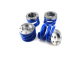
Mentioned earlier, the necessary tool can be either purchased for a modest outlay from a race equipment supplier, or made using nothing more exotic than a clutch slave cylinder, a 0 to 600 or 800psi hydraulic gauge, a short length of brake hose, and various pieces of metal. See relevant drawing for layout. Some form of adjustable spring platforms (read 'Hi-Los') are necessary - trying to do it with standard trumpets and shims is VERY laborious.
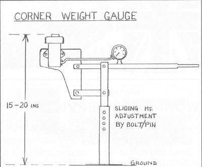 General layout of the corner-weight gauge for the DIY-er. Simple, effective, cheap.
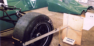
Dealing with the task goes like this. Set tyre pressures to desired readings. Disconnect any anti-roll bars fitted. Loosen any bolts passing through rubber suspension bushes (i.e. inner bottom arm mount). Dampers ideally disconnected, or set to softest point. This is to eliminate as far as possible any 'stiction' in the suspension components that would give inaccurate, inconsistent readings. Now set the car on previously manufactured flat pads as described in the 'Suspension - Basic set-up method' or on a perfectly level surface. Some folk at this point insert sheets of paper or thin sheets of metal/Lino tiles under the tyres - readings taken at the point where these can be pulled free. I used to. The enlightenment of a 'guru' some years later explained this to be unnecessary - a little 'bounce' is all that's needed. Position the gauge vertically with the pressure cylinder as far inside the wheel rim as is practicable at the 12 o'clock position. Slowly and firmly lean on the handle until the wheel is clear of the floor and then 'bounce' the handle gently once. Watch the needle. Take a reading at the point it stabilises. This doesn't vary a great deal whether the tyre's a whisker off the floor or 0.125"(3mm), and is certainly well within practical limits for our purposes.
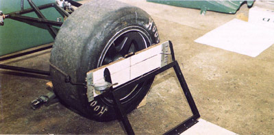
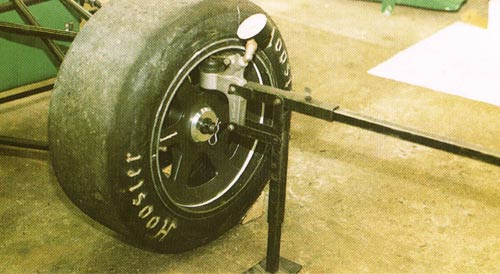 Corner weight gauge in use. Get that pressure cylinder as deep into the wheel rim as you can without obstructing use.
Make notes of the readings for each corner. To INCREASE the weight, RAISE the corner concerned by screwing whatever adjustable platform/cone you have CLOCKWISE. To reduce it do the opposite. Important point - always adjust two wheels (usually diagonally opposite) a little - and we're talking perhaps a 20 degree turn on a 'HiLo' adjuster here - rather than one a lot. This will avoid tantrums when getting one corner right, but throwing two others off, and doing weird things to your ride heights! If the car is really badly out (and I've encountered many of these), go back and re-set the ride heights by dumping the car as low as it'll go - then winch it up from there. Adjust each front/rear pair equally and again, adjust both a little in opposite directions rather than one by a lot. When set carefully - the corner weights shouldn't be miles out. Especially if you've made a decent attempt at counter-balancing solo driver weight. Once corner weights have been set - re-check/set the front suspension geometry. As previously stated, ride height alterations will change these.
The most complex part of this task is the mathematics - mainly caused by the weight bias problem. Instead of dealing with actual weights as would be the case in your archetypal single seater, percentages are involved. Don't be daunted - if you can use a calculator it's a cinch. Refer to the diagram for the low-down. As you go through these exercises you'll develop a 'feel' for how things go.
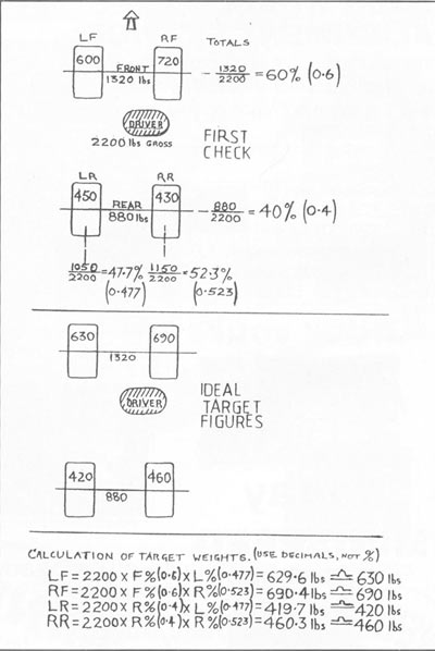 The mathematics needed for sorting what weight should be where. Perfection is Nirvahna, but with this equipment you should be able to get within 10lbs. For absolute accuracy you'll need £1500-worth of electronic remote read-out pads!
Ideally you need weighbridge-sourced figures for front/rear weight ratios together with a gross weight. But these are not essential. Effective results are achieved by simply adding the two front corners and two rear corners for a front/rear split percentage. And that's it. Told you it was simple. For really fine-tuning the car, tweaking of one corner by increasing it's load can be used to make the car pivot about a line joining that wheel and it's diagonally opposite partner. This is 'skewed roll' induced weight transfer - what the Americans call 'corner jacking'. Generally employed where cars race in circles/ovals with single direction corners and banked tracks.
Bump steer
This has to be the single most mis-understood term that crops up in conversations I have with racers from all spheres of motorsport. And of those that know what it is, few know what causes it or how to go about sorting it out. Entangled within the front suspension arms is the steering componentry. Their physical dimensions determine the arcs they move through whilst following the suspension movement. These arcs on a Mini are far from ideal as they're somewhat at odds with the actual suspension arm arcs. The result is any rise or fall at either front wheel (i.e. when going over bumps) causes them to independently change their pre-set and desired direction without driver input. This makes the car wander all over the place. Every bit as bad as it sounds, particularly when running a limited slip differential (LSD) as the wandering becomes pretty aggressive! The effects vary from a slight uncertainty in 'feel', inconsistent placement of the car in a corner, to severe instability both at speed and under acceleration/braking sufficient to give you white-knuckles and stained undies.
Equipment wise, again you can either invest a minor fortune (in 'budget racer land') in a pukka tool or make your own. Here there are two routes - dependent on accuracy required. I always hold to the ideal that if you're trying to achieve something - make sure it's as near exact as possible. Having said that, anything used to determine and reduce a problem has to be worth a shot. Duplicating the 'manufactured' equipment is relatively easy and inexpensive, requiring little more than a dial gauge, a piano-type hinge, some materials for the base board and wheel board, and a bungee. This'll be accurate to whatever the dial gauge reads in. The less accurate alternative is merely a piece of angle iron or extruded aluminium and a board. Examine the relevant illustrations for a better, visual illustration.
 Home-made bump steer gauge version one. Very basic but enough to illustrate the trouble you have, and help reduce it.
 Home-made bump steer gauge version two. Cheap, effective, and very accurate. The base-board has a hinged section to allow it to pivot. One top corner carries a dial gauge, the other a solid pin. The wheel board (made in metal or wood) is marked with measurements for bump and droop (rise and fall), centreline and static ride height. Once car is set as described in text on level area - Attach calibrated wheel board across approximate wheel centreline. Jack wheel up to static ride height. Set gauge leaning against wheel board both pin and dial gauge plunger on it's centred zero line and dial gauge in middle of its travel. Raise and lower wheel by jacking up/down bottom arm at 0.250"(6mm) increments. Note dial gauge readings at each point. Make (and record!) guessed changes, and repeat.
Carrying out the task starts with setting the car on your level surface - however contrived - then setting the chassis on blocks (front and rear to avoid discrepancies in a changed chassis attitude), with an extra 3" added. This is to allow the wheel to fall (droop). Remove/disconnect the rubber spring/any other spring; bump stops and dampers to facilitate easy raising/lowering of the wheel on its suspension. On a Mini using the original rubber springs, simply remove the ally trumpet (standard or HiLo). Place a jack under the bottom arm so you can raise and lower the arm and hold it in place whilst readings are noted. 0.250"(6mm) increments is enough.
Now how to make adjustments. Real racing cars are designed with the right steering rack length, with the right track-rod length, pivoting in the right places to minimise bump steer from the off. Achieved mainly by having the steering rack body level with the top suspension arm inner pivot points in a horizontal plane and the track rods pivoting at the same point as the upper arm inner pivot point. Only very minor adjustments are needed in the worst cases. Mass-produced production saloons rarely have this luxury, and our dear little Min is absolutely no exception, following the general practise of making the track rod as long as possible from inner pivot to steering arm. This ensures the track rod is moving through a much shallower arc than those described by the upper suspension arms, therefore reducing adverse effects. This is taken to new levels of extreme on modern cars where the track rods are very nearly (and in some cases more) than half the width of the car. The track variation is quite horrendous, the effects worsened by our determination to fit the widest wheels possible (see 'Suspension - KPO and the adverse effects caused by fitting wide wheels). Relocation or replacement for a more suitably dimensioned item isn't really on. Relocation extremely difficult to achieve satisfactorily, a more suitably dimensioned unit way too expensive and even then subject to the former to maximise the investment.
What's left is playing with the steering arm to track-rod connection/height. First off, you need to determine what needs to go where. The easiest way is to have a spare pair of steering arms with the track-rod end hole drilled out to 0.5" and screw a female 0.5"x0.5" spherical rod-end onto the track-rod in place of the standard one. Connect the two by a suitably long 0.5" bolt. Start out running a set of measurements (as depicted in the relevant illustration) for base-line data. Then place washers between the steering arm and rod-end (making sure the outside diameter of the washers does not interfere with the rod-end movement), and run a second set of measurements. Do both sides individually, as invariable on mass-produced cars they'll be different from side to side.
To convert this to a permanent fixture - you'll either need to make a spacer to the equivalent thickness of the spacers you've used, and retain the rod-ends (definitely the easiest option), or sort the standard steering arm to use the original track-rod end. It's possible to place shims under the steering arm, or machine the underside of the arm down - dependent on the direction required. WARNING - this should only be done to rectify a small amount of spacing. 0.125"(3mm) at the most to avoid mechanical failure. It's also possible to heat up then bend the arms. This has many problematic side effects - getting the amount exactly right, maintaining the Ackerman angle (don't - you really don't want to go there!), and ensuring structural integrity. To do this the arms should be cooled as slowly as possible by burying them in DRY sand and leaving them until they are cold.
The rod-end solution is the easiest, as stated. I always weld a nut to the rod-end to increase thread engagement on the track rod. You may not eliminate bump steer entirely simply by altering the track-rod end height - but certainly vastly reduce it.
Useful part numbers:
TOOL10 Caster/camber gauge
TOOL11 Tracking gauge
HILO Pair adjustable HILO suspension trumpets
HILO-01 Pair rear struts and plastic plugs to use HILO on rear
HILO-03 Front HILO adjusting key
HILO-04 Rear HILO adjusting key