
| Orig. Posting Date | User Name | Edit Date |
| May 25, 2014 12:54AM | DRMINI | Edited: May 25, 2014 01:00AM |
| May 24, 2014 10:14PM | zerobelow | |
| May 24, 2014 08:51PM | wilhite | |
| Apr 30, 2014 09:18AM | killrb | |
| Apr 30, 2014 06:24AM | mur | |
| Apr 30, 2014 12:15AM | killrb | Edited: Apr 30, 2014 04:41AM |
| Apr 29, 2014 05:07PM | mur | |
| Apr 29, 2014 04:35PM | killrb | Edited: Apr 29, 2014 04:58PM |
| Apr 29, 2014 12:28PM | minimans | |
| Apr 29, 2014 10:56AM | mur | |
| Apr 29, 2014 10:28AM | minimans | |
| Apr 29, 2014 10:01AM | mur | |
| Apr 29, 2014 07:25AM | dangparker | |
| Apr 28, 2014 08:48PM | killrb | |
| Apr 28, 2014 08:41PM | DRMINI | Edited: Apr 28, 2014 08:43PM |
| Apr 28, 2014 08:27PM | killrb | Edited: Apr 28, 2014 08:37PM |
| Apr 28, 2014 04:56AM | macmanron | |
| Apr 27, 2014 03:34PM | dklawson | |
| Apr 27, 2014 03:01PM | mur | |
| Apr 27, 2014 02:35PM | wilhite |
Found 26 Messages

|
Total posts: 8645
Last post: Dec 16, 2020 Member since:Oct 27, 2000
|
Cars in Garage: 0
Photos: 0 WorkBench Posts: 0 |
|
Question:
I've seen several suggestions (here and in the past) to use an external solenoid/relay. But the starter has an internal solenoid, too. Is the concern that sometimes, the starter's internal solenoid will stick closed?
It seems odd to me that we are using basically two relays/solenoids in series with eachother, with the first triggering and feeding the second. What's the thinking there?
I have recently gone through this, by necessity.
Most pre-engaged starters have a solenoid coil that drags way more juice than the little Lucas one did. This is because it has to throw the pinion into mesh, as well as closing the starting current circuit. The Mini start circuit on the ignition switch is light duty and cannot carry this solenoid coil current, it suffers voltage drop.
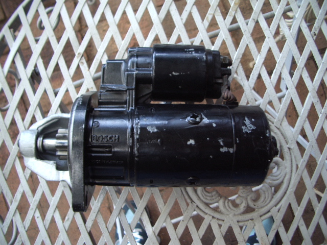
In my case with a modified Bosch starter off a 3.8L GM V6, the solenoid would not pull in reliably due to this voltage drop. So I wired it via the Lucas solenoid as described previously.
[edit] this one mounts with the solenoid below it, so you can use with an S oil cooler if wanted.
Kevin G
1360 power- Morris 1300 auto block, S crank & rods, Russell Engineering RE282 sprint cam, over 125HP at crank, 86.6HP at the wheels @7000+.
|
|
Total posts: 278
Last post: Jun 20, 2014 Member since:Oct 24, 2012
|
Cars in Garage: 0
Photos: 0 WorkBench Posts: 0 |
Question:
I've seen several suggestions (here and in the past) to use an external solenoid/relay. But the starter has an internal solenoid, too. Is the concern that sometimes, the starter's internal solenoid will stick closed?
It seems odd to me that we are using basically two relays/solenoids in series with eachother, with the first triggering and feeding the second. What's the thinking there?
|
|
Total posts: 473
Last post: Nov 21, 2019 Member since:Jun 29, 2011
|
Cars in Garage: 0
Photos: 0 WorkBench Posts: 0 |
|
I got as far as fitting the new starter up to the motor. The power connection bolt lines up way too close to the bottom of the dizzy. I'm getting a little annoyed with this project.
|
|
Total posts: 44
Last post: Jul 14, 2014 Member since:Feb 28, 2012
|
Cars in Garage: 0
Photos: 0 WorkBench Posts: 0 |
|
|
|
Total posts: 5840
Last post: Nov 1, 2019 Member since:Nov 12, 1999
|
Cars in Garage: 0
Photos: 0 WorkBench Posts: 0 |
|
My goal is to help people who have never installed a relay before learn how to do it and then be able to use that same skill over and over.
Note that I said your diagram is: ...is perhaps workable, but I would not do that...
Then I explained my position. Note how it is in line with my earlier post.
If a person does a google search they can find a nearly endless number of diagrams for relays, many of them show conflicting information. I'm trying to reduce the negative impact that conflicting information causes those at the start of the learning curve.
|
|
Total posts: 44
Last post: Jul 14, 2014 Member since:Feb 28, 2012
|
Cars in Garage: 0
Photos: 0 WorkBench Posts: 0 |
|
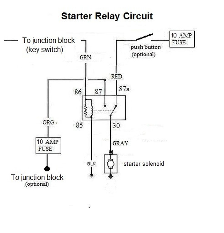
"#30 should be where power comes to the relay from the power source.
#87 should be where the load comes off the relay, to go and trigger the solenoid.
#87a should not be used"
When used with or without the junction terminal the relay shows the exact proper electrical connections. Below are the rebuttal remarks for your suggestions.
Considering # 30> It does not matter which terminal of the relay goes to positive (powered) be it #30 or #87a. The relay will close in either circumstance and the optional push button will still work in it's static mode. If you open up a relay you will see that the contacts are the same on either side of the switch and the relay is not polarity conscious. There are relays that are polarity conscious but not needed in these circumstances. The switch circuit from #30 and #87a does not even need to be powered, after all it's just a switch. In this circumstance , however, it is powered to energize the starter solenoid manually as an option. Your suggestion would power on the starter solenoid all the time unless you changed the position of the affected parts in the drawing. I'm sure you meant to say that. I think you need to clarify your position in this circumstance or perhaps draw the circuit the way you see it and I can opinionate your work as a means of serving this forum as you have done to my work.
Considering # 87> Not significant. It matters not which side of the relay switch has the load on it, #87 or #30. I drew it to make it simpler to read. The coil triggers the relay the switches carry the load.
Considering 87a > This terminal is the only terminal that can be used to switch to the load because the relay is normally in the off position and switches to # 87 when the coil of the solenoid is activated. The optional push button will not activate the starter unless it is pushed. The relay is only activated as long as the starter switch is physically engaged otherwise.
Maybe you are just to much of a purist to realize that improving a Mini electrical system and modern parts replacement is not sacrificial. The relay diagram is every bit of correct and was placed there for other members benefit as well as yours if you choose. I don't understand why some members would seemingly attack the very suggestion that would help others. I hope you understand that this is a matter of clarifying a situation that has came to your attention. It is nice to know that you have a Mini that is that reliable. I suppose that the company might accidentally turn out a one in a million faultless product. For all the miles you claimed was free, I can imagine a million other miles per 1000 that other owners have placed on their cars and have not been driven under the same fortunate circumstances as your car has. Just letting you know how I perceive the situation just as you perceived yours.
BTW, I am not an MGB V8 fellow. I own at least 3 Mini's and have owned at least 10 others. I do own several MGB's that have engine changes but the work is meticulous and pristine. I do own British Car Conversions, however, and we modify and improve the quality of the British automobile without the sacrilege of cutting them up or modifying the body work shamelessly. Our products are recognized in all 50 states and throughout the North American continent and abroad. I am in a position to take great criticism from many who have experience with British cars, so I try to be as thorough as possible. It takes a great deal of time to present these infrequent articles on this forum but I do enjoy helping others of lesser experience. Mistakes are always ever present and part of this forum is to stimulate the members into making suggestions in order to bring a satisfactory conclusion to all that is written technically.
I wonder how many people will jump on this and say I was being antagonistic again.
|
|
Total posts: 5840
Last post: Nov 1, 2019 Member since:Nov 12, 1999
|
Cars in Garage: 0
Photos: 0 WorkBench Posts: 0 |
|
I have always found the Lucas Darkness and Smoke jokes tiresome. I daily drove a mini for twenty+ years and my mini road trip summer vacation generally involves more miles than most people drive in a year. My mini isn't a clown car. Lucas parts have been more reliable than Delco, Denso, Fomoco, etc. in my experience. My last Lucas failure, after 50 000+ miles on an alternator, had no discernable effect on a 500 mile day. I follow a board for Landcruiser and LX470 lexus SUVs and when those kids lose their alternators it is as though the world has ended.
Now, the diagram that the MGB V8 fellow proposes is perhaps workable, but I would not do that.
#30 should be where power comes to the relay from the power source.
#87 should be where the load comes off the relay, to go and trigger the solenoid.
#87a should not be used
a momentary switch to trigger the starter should connect to #86, the same as the starter signal wire from the ignition switch. If there is a conflict there, and the start portion of the ignition switch powers other items in the car, then you could just as easily run the momentary switch power straight to the starter solenoid. In the above diagram the momentary switch gains nothing by going through the relay.
|
|
Total posts: 44
Last post: Jul 14, 2014 Member since:Feb 28, 2012
|
Cars in Garage: 0
Photos: 0 WorkBench Posts: 0 |
|
Dann, British Car Conversions
|
|
Total posts: 1404
Last post: Jun 21, 2018 Member since:Oct 8, 2013
|
Cars in Garage: 0
Photos: 0 WorkBench Posts: 0 |
Is that from a joke from 1985?
Yes it is I'm old so are all of my jokes!!
Mini's are like buses they come along in a bunch
|
|
Total posts: 5840
Last post: Nov 1, 2019 Member since:Nov 12, 1999
|
Cars in Garage: 0
Photos: 0 WorkBench Posts: 0 |
|
Is that from a joke from 1985?
|
|
Total posts: 1404
Last post: Jun 21, 2018 Member since:Oct 8, 2013
|
Cars in Garage: 0
Photos: 0 WorkBench Posts: 0 |
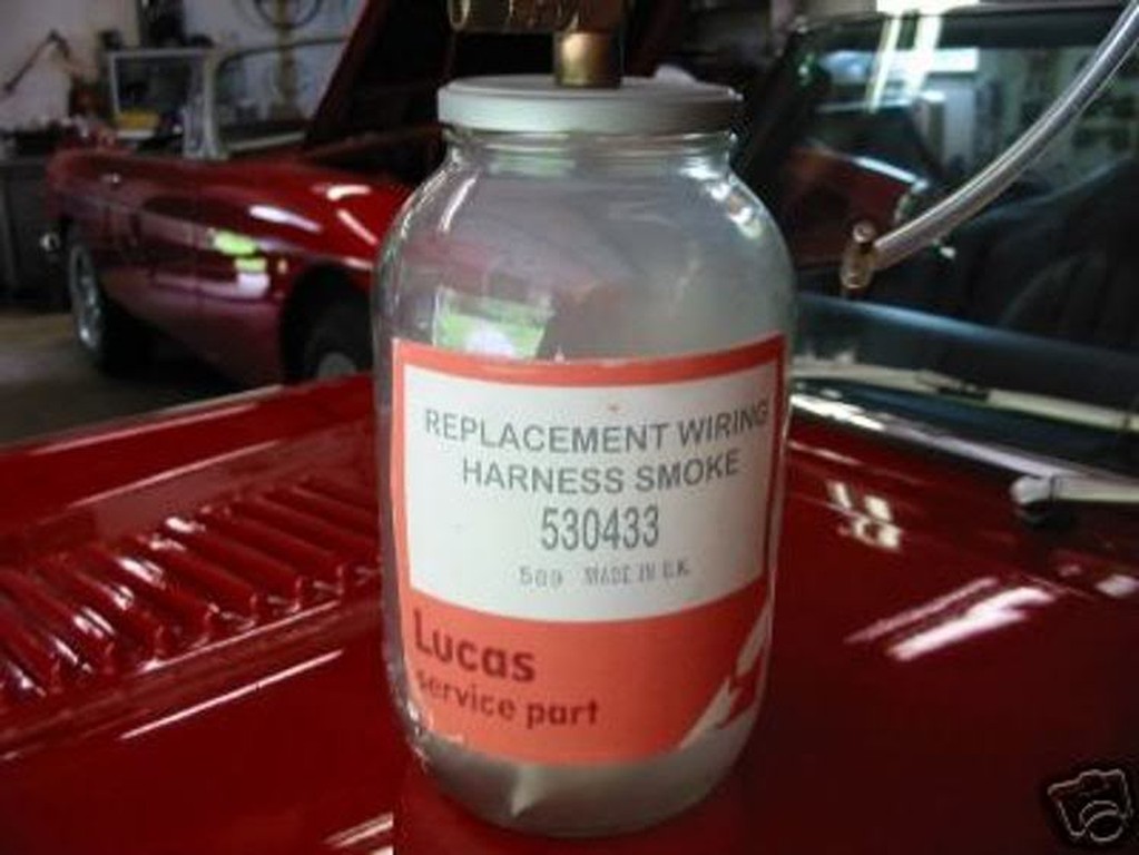
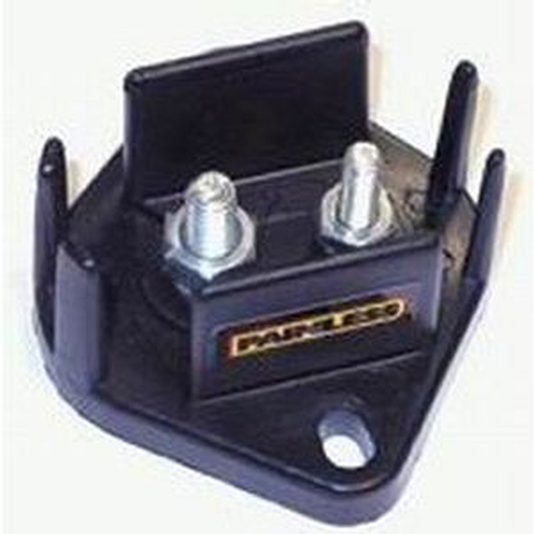
And if by chance you do let the smoke out of something you will need one of these........................
Mini's are like buses they come along in a bunch
|
|
Total posts: 5840
Last post: Nov 1, 2019 Member since:Nov 12, 1999
|
Cars in Garage: 0
Photos: 0 WorkBench Posts: 0 |
|
I changed a harness in a 1990 mini. It had a brand new ignition switch and lock assembly. It would not reliably operate the pre engaged starter. The relay was necessary.
A person can find endless relay diagrams on the internet. Something to watch for is the ordering of the terminals on the relay. Some exchange #85 and #86 back and forth, but generally use #85 for ground. # 86 for +12V to trigger the relay, #30 for the source +12V power to operate the appliance and #87 for the load of the appliance you are powering via the relay.
The best way to learn though is to do. Go to the local auto parts store and buy a relay and a wiring block and use it to power something like a horn or the headlamps.
Also, post #87a on a relay is powered when the relay is NOT triggered. Some relays have this, it can be useful.
Another thing to think about is that you can trigger the relay with the #85 ground terminal. Keep terminal #86 powered all of the time and then just send a switched ground out to the relay. Any wire you run then isn't actually powered, so if you make some rookie error it won't have consequences.
|
|
Total posts: 23
Last post: May 11, 2017 Member since:Apr 7, 2012
|
Cars in Garage: 0
Photos: 0 WorkBench Posts: 0 |
Cheers and thanks!
Daniel
|
|
Total posts: 44
Last post: Jul 14, 2014 Member since:Feb 28, 2012
|
Cars in Garage: 0
Photos: 0 WorkBench Posts: 0 |
|
|
|
Total posts: 8645
Last post: Dec 16, 2020 Member since:Oct 27, 2000
|
Cars in Garage: 0
Photos: 0 WorkBench Posts: 0 |
|
I wired my Bosch geared one like that originally, and it didn't work consistently. 1/2 the time the starter would just spin without engaging the ring gear. Too much voltage drop through the keyswitch `start' wiring....
[edit] I guess it depends on how biga$$ the starter is- I have wired plenty of Isuzu Gemini starters into Minis your way, without a problem.
Kevin G
1360 power- Morris 1300 auto block, S crank & rods, Russell Engineering RE282 sprint cam, over 125HP at crank, 86.6HP at the wheels @7000+.
|
|
Total posts: 44
Last post: Jul 14, 2014 Member since:Feb 28, 2012
|
Cars in Garage: 0
Photos: 0 WorkBench Posts: 0 |
|

|
|
Total posts: 2935
Last post: Jan 13, 2022 Member since:Apr 28, 2003
|
Cars in Garage: 5
Photos: 59 WorkBench Posts: 7 |
|
|
|
Total posts: 9241
Last post: Aug 17, 2023 Member since:Jun 5, 2000
|
Cars in Garage: 0
Photos: 0 WorkBench Posts: 0 |
|
Dean, I have no idea what the little screw is for. I am assuming that the trigger wire connection is the spade terminal in the plastic housing shown in your first post.
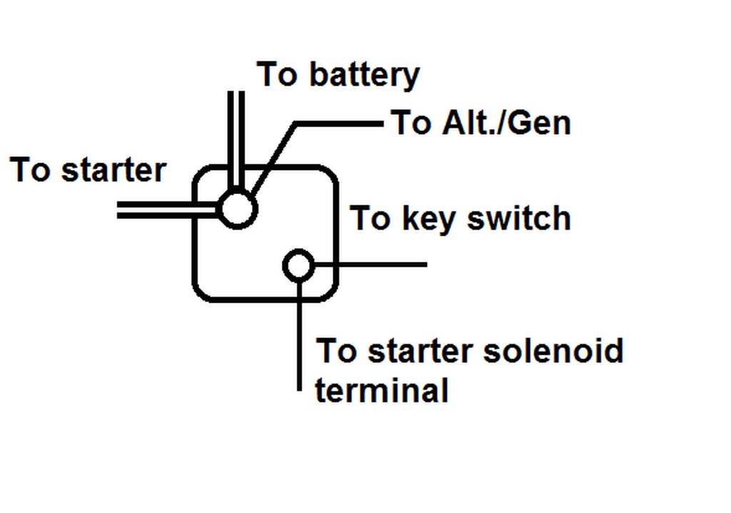
Actually Kevin's wiring is different than what I was suggesting. He is saying to move the old starter motor cable over to the solenoid terminal where the battery cable connects... then connect the other end of the old starter cable to the new starter. From the threaded stud on the old solenoid (that has nothing on it once you remove the old starter cable) run a heavy gauge wire over to the new starter's trigger terminal. Kevin's method just uses the old solenoid for a heavy duty relay for the trigger signal.
Mur's suggestion is basically turning the wiring into what later model Minis had with a starter relay. You would still move the old starter motor cable as Kevin suggested so it would become a junction box. Then you would put in a heavy-duty relay somewhere in the engine bay. The white/red wire from the old solenoid woud be used as a trigger to close the relay and when the relay is closed it would pass current from the old solenoid's battery cable terminal to the trigger terminal on the new starter motor.
There are many options. On our GT6 I did as I described in my first post as it was absolutely the simplest for me. However, going along with Mur's comments about solenoid quality... our GT6 currently has a Ford Mustang solenoid, not a Lucas unit.
|
|
Total posts: 5840
Last post: Nov 1, 2019 Member since:Nov 12, 1999
|
Cars in Garage: 0
Photos: 0 WorkBench Posts: 0 |
|
I think that remote solenoids are pretty unreliable anymore. I'd say this as a mini guy who has seen many of them fail lately, especially anything made for minis in the last while, but also I have changed more than a few in the last while on the fleet of generators I look after.
The manufacturing went offshore, and the quality fell to bits.
Still, a solenoid on a modern starter isn't besotted with this, and they are pretty reliable.
For me, it makes sense to apply layers of really dependable things into systems. Both Doug and Kevin's solutions should be excellent, but for a mini in Oklahoma I'd totally trigger that new starter with a Hella relay, and it would be hella good.
|
|
Total posts: 473
Last post: Nov 21, 2019 Member since:Jun 29, 2011
|
Cars in Garage: 0
Photos: 0 WorkBench Posts: 0 |
|
Kevin it sounds like you said the same thing that Doug said.
And what hat about the little screw on the bottom?
Found 26 Messages


