
| Orig. Posting Date | User Name | Edit Date |
| Nov 30, 2014 08:12PM | Shrimps | |
| Nov 30, 2014 06:22PM | dklawson | |
| Nov 30, 2014 05:34PM | Shrimps | |
| Nov 30, 2014 03:23PM | dklawson | |
| Nov 30, 2014 02:00PM | Shrimps | |
| Nov 30, 2014 01:42PM | Dan Moffet | |
| Nov 30, 2014 08:18AM | Shrimps | |
| Nov 29, 2014 05:12PM | dklawson | |
| Nov 29, 2014 04:05PM | mur | |
| Nov 29, 2014 03:20PM | jeg | Edited: Nov 29, 2014 03:31PM |
| Nov 29, 2014 03:16PM | Cup Cake | |
| Nov 29, 2014 03:06PM | Shrimps | |
| Nov 29, 2014 02:50PM | Dan Moffet | |
| Nov 29, 2014 02:13PM | Shrimps |

|
Total posts: 328
Last post: Jun 9, 2018 Member since:Sep 28, 2010
|
Cars in Garage: 1
Photos: 67 WorkBench Posts: 0 |
|
All makes sense. I don't have a ballast coil so that's why I'm bypassing the ballast resistor wiring.
|
|
Total posts: 9241
Last post: Aug 17, 2023 Member since:Jun 5, 2000
|
Cars in Garage: 0
Photos: 0 WorkBench Posts: 0 |
|
Actually the Pertronix unit has no problem at all with a ballast ignition coil. However, if you kept the ballast ignition coil you would have to power the ignitor module from a switched full 12V supply off the fuse box (Pertronix red wire to fuse box... not to coil (+)).
You can leave the wire from the 4th solenoid terminal connected if you want. When you have installed the new 12V coil it is no longer needed but just like the pinkish wire... it won't hurt anything to leave it connected.
|
|
Total posts: 328
Last post: Jun 9, 2018 Member since:Sep 28, 2010
|
Cars in Garage: 1
Photos: 67 WorkBench Posts: 0 |
|
When running my own unfused lead from the fuse block will I still need to run a lead from the 4th "cranking" terminal of the solenoid? The white lead off the fuse block has 12v when cranking so I'm thinking not but thought I'd check.
Thanks again for the help. I finally understand how the ballast ignition differs from a non-ballast'd. I'd use it but the Pertronix doesn't like it so I'll work around it. I'll keep the wiring in place though for possible future use just in case.
|
|
Total posts: 9241
Last post: Aug 17, 2023 Member since:Jun 5, 2000
|
Cars in Garage: 0
Photos: 0 WorkBench Posts: 0 |
|
I'm currently working on running running a separate switched +12v to the coil & am going to abandon the ballast resistor.
That is a very common change to make. Most people find the white wire at the fuse box and run an extension of it (unfused as Dan said) to coil (+). That will give your standard 3 Ohm coil the correct supply voltage it needs. You can leave the old supply wire on coil (+) or remove it and tape its terminal off so it cannot touch ground. (With your new supply wire providing 12V it will not hurt to leave the old wire in place if you want to.)
I like ballast ignitions but the pinkish wire has been the source of so many complaints and failures I understand why people don't want to use them.
|
|
Total posts: 328
Last post: Jun 9, 2018 Member since:Sep 28, 2010
|
Cars in Garage: 1
Photos: 67 WorkBench Posts: 0 |
|
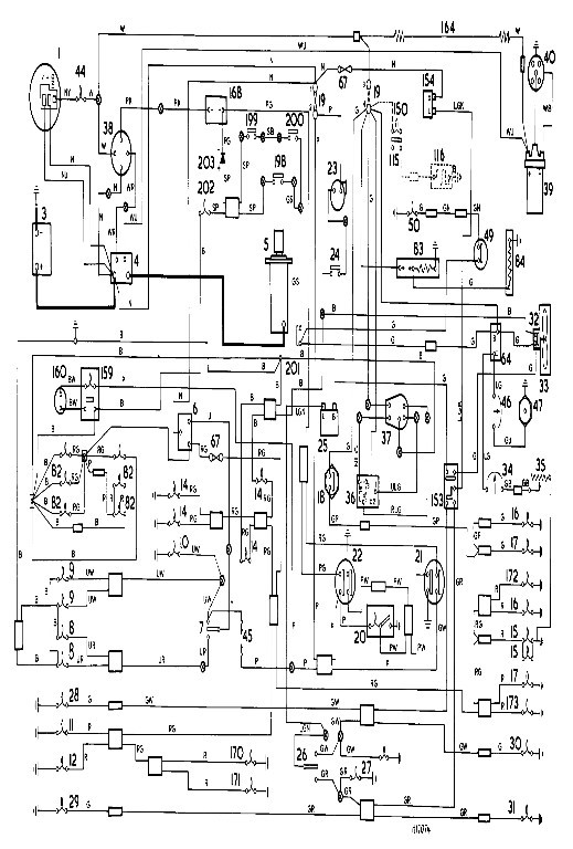
You're correct Dan except my car is a MkIII so I'm using Haynes diagram page 12.26 which matches my Prospero's color diagram which shows white ballast wire & white/blue trace to solenoid which matches my car wiring.
I'm currently working on running running a separate switched +12v to the coil & am going to abandon the ballast resistor.
|
|
Total posts: 9845
Last post: May 23, 2025 Member since:Aug 14, 2002
|
Cars in Garage: 0
Photos: 0 WorkBench Posts: 0 |
|
Thanks for all the replies. The car does have a 4 terminal starter solenoid. I checked voltage per Doug's instructions & am getting 7.5v so as the wiring diagram indicates I do have a ballast resistor somewhere.
But nowhere does the diagram show I should have a pink wire though. The diagram shows white going to the ignition though the resistor & white/blue to solenoid. Only pink wire I see on the diagram is from ignition to ignition key buzzer.
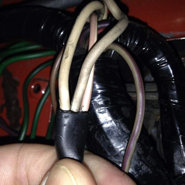
I did spy this tucked up under the cowl: two sizable whites & pink w/white. Is this part of the ballast resistor perhaps?
At this point it looks like I'll run a new wire from the white lead at the fuse block (12v when key is ON) and abondon the original white wire that has the resistor.
Do I need to keep the white w/blue from the starter solenoid connected to + side of coil? I'm thinking so to make sure I'm getting 12v during cranking but want to make sure having three connections on the + side of coil is ok (switched 12v, cranking 12v & Pertronix red lead).
According to Haynes, page 12.32 - MIni 1000 Canadian 1977 onwards, the ballasted wire should be white with pink trace "WK" wire. The wie IS the ballast - that is it is a wire of a specific resistance tor reduce the voltage. It should originate at the hot (unfused) side of the ingnition switch controlled fuse. Hot side so the engine does not die if the fuse blows.
You should also have a white with a blue trace "WU" which is regular wire coming form the extra solenoid terminal.
Both these connect to the coil + terminal, and there should be only a white/black trace from the - (neg) terminal to the side of a standard dizzy. If you have a tach wire, it would also be white/black and on the -(neg) terminal.
Somewhere in that vicinit you should also have wires leading to the alernator, which should include brown/yellow trace (NY) - coming from the charge light, a plain brown and a brown/blue (NU) -both going to a the solenoid terminal connected directly to the battery.
I can't spot any white/purple trace in amy wiring diagrams though.
.
"Hang on a minute lads....I've got a great idea."
|
|
Total posts: 328
Last post: Jun 9, 2018 Member since:Sep 28, 2010
|
Cars in Garage: 1
Photos: 67 WorkBench Posts: 0 |
|
Thanks for all the replies. The car does have a 4 terminal starter solenoid. I checked voltage per Doug's instructions & am getting 7.5v so as the wiring diagram indicates I do have a ballast resistor somewhere.
But nowhere does the diagram show I should have a pink wire though. The diagram shows white going to the ignition though the resistor & white/blue to solenoid. Only pink wire I see on the diagram is from ignition to ignition key buzzer.
I did spy this tucked up under the cowl: two sizable whites & pink w/white. Is this part of the ballast resistor perhaps?
At this point it looks like I'll run a new wire from the white lead at the fuse block (12v when key is ON) and abondon the original white wire that has the resistor.
Do I need to keep the white w/blue from the starter solenoid connected to + side of coil? I'm thinking so to make sure I'm getting 12v during cranking but want to make sure having three connections on the + side of coil is ok (switched 12v, cranking 12v & Pertronix red lead).
|
|
Total posts: 9241
Last post: Aug 17, 2023 Member since:Jun 5, 2000
|
Cars in Garage: 0
Photos: 0 WorkBench Posts: 0 |
|
This post is just to elaborate on what has already been said by others above.
IF you have a factory ballast ignition, the coil (+) terminal will be supplied by a pink/white (pinkish) wire. Sometimes it is hard to tell based on color. You can measure the voltage on the coil to determine what is present if wire color alone does not tell you. HOWEVER, you cannot just stick a voltmeter on the coil. Current MUST be flowing through the coil when the voltage measurement is made.
To make the coil voltage measurement, connect a jumper wire from coil (-) to ground. Connect your volt meter between coil (+) and ground. Turn the ignition key to the run position and read the meter. If you find battery voltage (nominally about 12.5V) you have a standard ignition system. If you measure 6V to 9V, your car's wiring has a ballast resistor or resistor wire installed.
|
|
Total posts: 5840
Last post: Nov 1, 2019 Member since:Nov 12, 1999
|
Cars in Garage: 0
Photos: 0 WorkBench Posts: 0 |
|
In answer to your query:
You need +12V for the Pertronix. I can not tell from the photo if there is a pink tracer on the coil positive, so measure the voltage, less than what the alternator is putting out means YOU NEED TO RUN A NEW WIRE. As you can see, the car will run with the lower voltage headed to the system but with devices made for full voltage you should give them full voltage.
|
|
Total posts: 7075
Last post: Nov 5, 2019 Member since:Apr 25, 2000
|
Cars in Garage: 0
Photos: 0 WorkBench Posts: 0 |
|
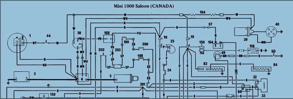
I converted to a ballast system and a 1.5Ω coil in 2010 prior to installing the optical ignition. Since my mini originally used the standard 3-terminal solenoid and a 3Ω coil, I changed to the 4-terminal solenoid used in Metros and I suspect, Canadian minis.
Going on memory here, but if I recall correctly, the white wire from the fuse block is not ballasted with an internal resistor; this would be pink if it had the internal resistor.
I installed the ballast resistor between the + coil terminal and the W wire which runs directly to the fuse block. I connected the '4th' terminal of the starter solenoid directly to the ignition coil (Bosch GT40R) to give the full 12V during cranking.
I haven't a Pertronix, so check the Pertronix schematic, but in my Luminition Optronic, the red wire gets connected to the ballast resistor; piggy-backed to the 'W' ignition wire, not the coil side of the resistor.
In this image, # 164 is the ballast resistor:
 The peasants are revolting...
 ![]()
"Gone with the Wind" - a brief yet moving vignette concerning lactose intolerance
|
|
Total posts: 10335
Last post: Aug 19, 2016 Member since:May 13, 2001
|
Cars in Garage: 0
Photos: 0 WorkBench Posts: 0 |
|
With a 3ohm coil no ballast resistor is required. You want 12v all the time, so you don't need the ballast wire. The reason for this is the Ignitor I maximum current is ~4 amps otherwise it will burn out. Even then you don't want to leave the key in the on position for more than a few minutes, for example, when setting the spark advance.
The power of accurate observation is commonly called cynicism by those who have not got it. G.B.S. Sarcasm is the lowest form of wit. Oscar Wilde
//www.cupcakecooper.ca/
|
|
Total posts: 328
Last post: Jun 9, 2018 Member since:Sep 28, 2010
|
Cars in Garage: 1
Photos: 67 WorkBench Posts: 0 |
|
Pertronix documentation says if you've got an external ballast resistor to connect the red Pertronix wire to the ignition lead prior to the ballast resistor. Anybody know where the ballast resistor is actually located? Or can I find some other +12v lead that's hot when the key is "On"?
|
|
Total posts: 9845
Last post: May 23, 2025 Member since:Aug 14, 2002
|
Cars in Garage: 0
Photos: 0 WorkBench Posts: 0 |
|
The typical ballasted system has both wires conneced to the same terminal on the coil. The 12V supply from the solenoid only provides curent while the solenoid (and key) is in the "crank engine" position. The other ballasted/resistance wire is connected to the normal ignition circuit and is energized in the "engine on" position via the ignition switch> at th switch it is 12V but because of the resistance in the wire, only 9V or so comes out to the coil.
As for the Petronix unit, do the specs say it will function on the lower voltage? I think the anwer to the red wire question is probably "yes".
.
"Hang on a minute lads....I've got a great idea."
|
|
Total posts: 328
Last post: Jun 9, 2018 Member since:Sep 28, 2010
|
Cars in Garage: 1
Photos: 67 WorkBench Posts: 0 |
|

MkIII Canadian Mini 1000: I bought car with a thin flange Cooper S 1275 engine with Pertronix ignitor & 3 ohm 40K volt coil. Didn't run engine much due to knackered thrust washers but it did indeed run. Fast forward to today where I am installing a 998 out of my MkIV that also has Pertronix & 3 ohm coil.
My question is if I need to do anything special due to car having a ballast resistor (according to Haynes diagram which matches car wiring)? I've got two leads via one connection that connect to + side of coil (see picture). One is the ballast lead from ignition (white) and the other (white/blue) comes from starter solenoid.
Since one lead is coming from starter solenoid will that supply the needed 12v to the coil & make the Pertronix happy? Or will I need to connect the red lead from Pertronix to the ignition lead upstream of the ballast resistor as their supplied instructions indicate?
I have no confidence that the way is was wired before was correct thus I am here.
Thanks.


