

| Orig. Posting Date | User Name | Edit Date |
| Jul 30, 2016 01:00PM | Dan Moffet | |
| Jul 30, 2016 07:02AM | h_lankford | |
| Jul 29, 2016 09:36AM | Dan Moffet | |
| Jul 29, 2016 08:38AM | spectre1275 | |
| Jul 29, 2016 06:41AM | Dan Moffet | |
| Jul 28, 2016 05:10PM | spectre1275 | Edited: Jul 28, 2016 05:14PM |
| Jul 28, 2016 04:06PM | spectre1275 | |
| Jul 28, 2016 04:01PM | minibitz | |
| Jul 28, 2016 03:27PM | spectre1275 | |
| Jul 28, 2016 03:07PM | spectre1275 | |
| Jul 28, 2016 02:52PM | dklawson | |
| Jul 28, 2016 02:18PM | spectre1275 |

|
Total posts: 9845
Last post: May 23, 2025 Member since:Aug 14, 2002
|
Cars in Garage: 0
Photos: 0 WorkBench Posts: 0 |
|
The worst part is it it has been to darned hot for me to get the Mini out. Poor thing is still in winter hibernation mode. Soon...
PS. Sorry for the unintended hijack!
.
"Hang on a minute lads....I've got a great idea."
|
|
Total posts: 2040
Last post: Mar 20, 2025 Member since:Aug 29, 2001
|
Cars in Garage: 0
Photos: 0 WorkBench Posts: 0 |
|
|
|
Total posts: 9845
Last post: May 23, 2025 Member since:Aug 14, 2002
|
Cars in Garage: 0
Photos: 0 WorkBench Posts: 0 |
|
A "few seconds' later in recovery, when I told the nurse I was disappointed I missed what was going on, she said "you snored!"
Still, it is a neat bit of kit.
.
"Hang on a minute lads....I've got a great idea."
|
|
Total posts: 807
Last post: Sep 9, 2024 Member since:Oct 22, 2002
|
Cars in Garage: 0
Photos: 0 WorkBench Posts: 0 |
|

It's how I've always learned best, for better or worse. It helps that I generally have a backup plan (like $$ to buy a new one if things go sideways, or a spare of the thing I'm breaking).
Scott
New Zealand - The only place where a kiwi can mean a fruit, bird or mini owner...
|
|
Total posts: 9845
Last post: May 23, 2025 Member since:Aug 14, 2002
|
Cars in Garage: 0
Photos: 0 WorkBench Posts: 0 |
|
.
"Hang on a minute lads....I've got a great idea."
|
|
Total posts: 807
Last post: Sep 9, 2024 Member since:Oct 22, 2002
|
Cars in Garage: 0
Photos: 0 WorkBench Posts: 0 |
|
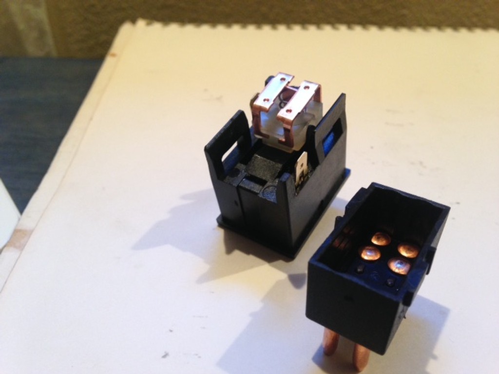
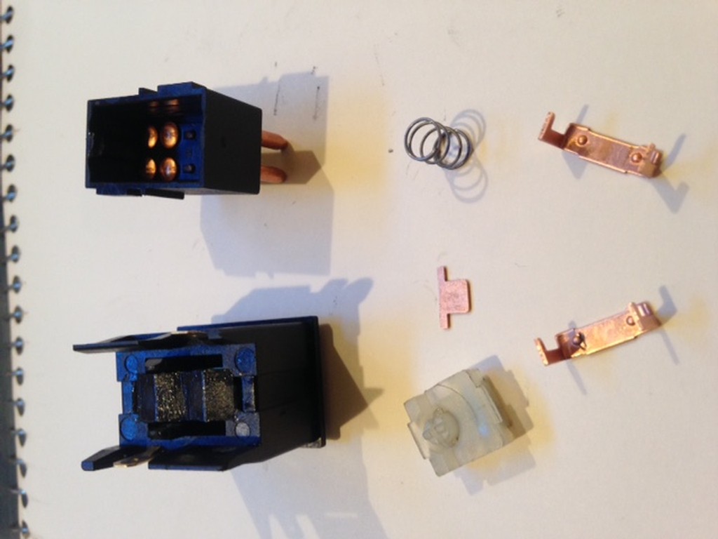
The one picture shows how the innards go together.
First, place the spring on the white plastic block in the obvious place, and then place the small "t" shaped copper piece onto the spring, so the base of the "t" goes in the spring, and the arms rest on top of the spring.
Then, take the two squarish copper pieces, and place them ON TOP of the "T" shaped piece, and push them down together so that the little feet of the squarish pieces engage on the lip of the plastic piece. You can see this in the first picture.
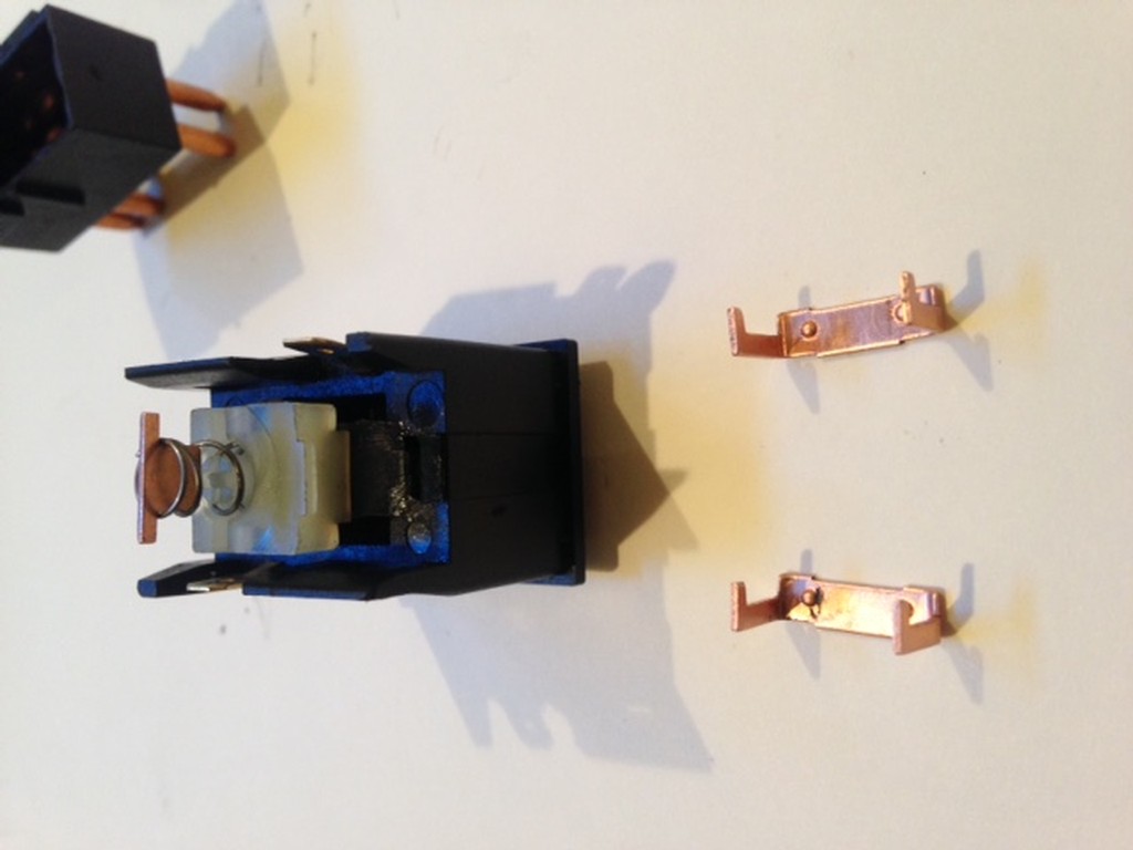
Then, gently (the feet will hold everything together), place it into the half of the switch which has the rocker you use to turn the hazards on and off. The plastic arms from that rocker will fit into rounded cutouts in white plastic piece.
Then, gently press the other half of the switch on top, pushing it down until the tabs on the side engage.
Ta-dah! Just saved $35 (plus shipping) for a new switch!
Scott
New Zealand - The only place where a kiwi can mean a fruit, bird or mini owner...
|
|
Total posts: 807
Last post: Sep 9, 2024 Member since:Oct 22, 2002
|
Cars in Garage: 0
Photos: 0 WorkBench Posts: 0 |
|
Scott
New Zealand - The only place where a kiwi can mean a fruit, bird or mini owner...
|
|
Total posts: 382
Last post: Apr 23, 2025 Member since:Jul 26, 2010
|
Cars in Garage: 0
Photos: 0 WorkBench Posts: 0 |
|
|
|
Total posts: 807
Last post: Sep 9, 2024 Member since:Oct 22, 2002
|
Cars in Garage: 0
Photos: 0 WorkBench Posts: 0 |
|
Do you know what the male spade connectors on the side of the switch are for, and the single green wire coming out of the harness right at the hazard switch coupling? Seems just long enough to slot on to that side spade, but I haven't seen any wiring diagrams that call out that that connection is.
Scott
New Zealand - The only place where a kiwi can mean a fruit, bird or mini owner...
|
|
Total posts: 807
Last post: Sep 9, 2024 Member since:Oct 22, 2002
|
Cars in Garage: 0
Photos: 0 WorkBench Posts: 0 |
|
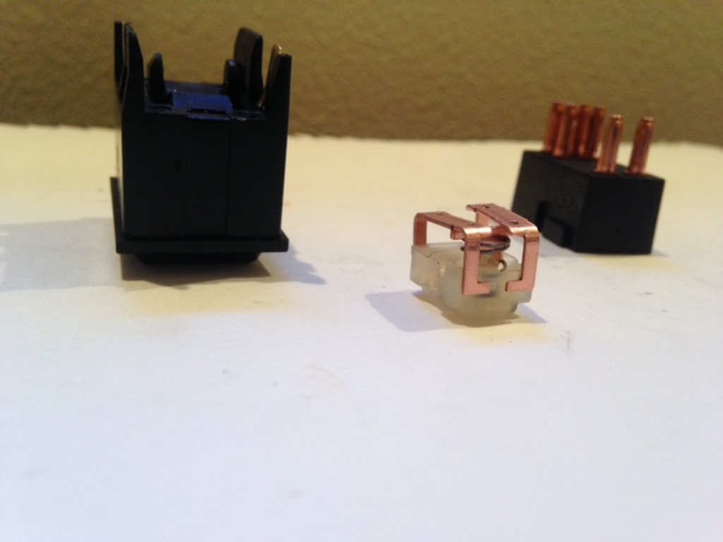
Of course, I wasn't expecting the spring inside that made all of the internals fall out on the table! Now I have a small pile of parts that I need help getting back together. I've searched on the net, and it seems no one has posted a picture of the switch, and how the pieces fit - anyone on the board here have an idea?
One picture are the parts I have, the other is how I think they *might* go together, though there are several ways the two copper bits in front could go on.
Anyone taken one of these apart that could lend some quidance, or do I need to shell out the $35 for a new one? (damn my curiosity!!)
Scott
New Zealand - The only place where a kiwi can mean a fruit, bird or mini owner...
|
|
Total posts: 9241
Last post: Aug 17, 2023 Member since:Jun 5, 2000
|
Cars in Garage: 0
Photos: 0 WorkBench Posts: 0 |
|
I'll try and be brief with the system description. The hazard switch does two things. When the key is in the run position and the hazard switch is OFF it passes power THROUGH to the turn signal flasher. When ON, the hazard switch breaks the current flow to the turn signal flasher and ties the left and right side light wires together so all the bulbs flash together.
Therefore, there should be unswitched power going into the hazard switch (brown or purple wire... probably brown) for the hazard relay to function and there should be a switched source (green wire) going into the hazard switch and out again going to the turn signal flasher.
Please look at the 75/76 MGB schematic in the middle of the PDF document linked below.
//www.advanceautowire.com/mgb.pdf
The hazard and flasher relays are in the bottom right corner above the title block.
Zoom in on the schematic noting the wire colors and switch & flasher terminal numbers/letters. Note that the turn signal flasher does not get its own direct power source but gets power after it passes through the hazard switch. This wiring schematic is pretty much common with all British cars so don't freak out that this is for an MGB. There may be some minor differences but you will be able to resolve them by looking at your car's specific wiring diagram.
You mentioned terminals X and L. That suggests you are using a U.S. type flasher instead of Lucas. That's fine. L still matches L, X will correspond to B in the schematic linked above.
|
|
Total posts: 807
Last post: Sep 9, 2024 Member since:Oct 22, 2002
|
Cars in Garage: 0
Photos: 0 WorkBench Posts: 0 |
|
Found that of the 4-5 old speedos I have, I installed the ONE that doesn't work. So, while I have the dash apart and am rebuilding the carb, thought I'd try to find why my turn signals don't work.
First off, my emergency flasher switch works, and all bulbs light up when on (that's good!)
However, with the new two pronged mechanical flasher installed, with the live feed wire hooked to "X" and the light green/brown turn signal wire hooked to "L", when I flip the stalk switch - hello! Emergency flasher results (all lights blinking brightly).
Thoughts? This happens without the key in the ignition, so that's one thing (I believe turn signals are only supposed to work with the key in the I or II position, correct?)
The emergency switch seems fine (it's new), but I do have a question about the green wire on the harness side - I'm expecting this should go to one of the male spade terminals on the side of the switch, but which one, and what does it do? Leaving it off doesn't seem to affect the performance of the emergency flashers - maybe the light in the switch (which if so, mine's not working)?
Thanks!
Scott
New Zealand - The only place where a kiwi can mean a fruit, bird or mini owner...


