
| Orig. Posting Date | User Name | Edit Date |
| Jun 2, 2019 09:26AM | dklawson | |
| Jun 2, 2019 06:08AM | Jamison70 | |
| Apr 21, 2019 04:08PM | dklawson | Edited: Apr 22, 2019 05:40AM |
| Apr 21, 2019 11:57AM | Jamison70 | |
| Apr 19, 2019 02:59PM | JayA1010 | |
| Apr 19, 2019 02:44PM | dklawson | Edited: Apr 19, 2019 03:17PM |
| Apr 19, 2019 02:11PM | Jamison70 | |
| Apr 16, 2019 06:59PM | dklawson | Edited: Apr 17, 2019 04:51AM |
| Apr 16, 2019 05:53PM | Jamison70 | |
| Oct 31, 2018 06:53AM | Spitz | |
| Oct 30, 2018 06:35PM | dklawson | |
| Oct 30, 2018 02:47PM | Jamison70 | |
| Oct 30, 2018 02:19PM | dklawson | |
| Oct 30, 2018 07:50AM | swindrum | Edited: Oct 30, 2018 07:55AM |
| Oct 26, 2018 07:50PM | dklawson | |
| Oct 26, 2018 04:57PM | Jamison70 | |
| Oct 26, 2018 03:15PM | dklawson | |
| Oct 26, 2018 01:43PM | Jamison70 |

|
Total posts: 9241
Last post: Aug 17, 2023 Member since:Jun 5, 2000
|
Cars in Garage: 0
Photos: 0 WorkBench Posts: 0 |
|
... but it turns out the distributor was bad. I finally gave up and took the car to a local MG expert and he figured that out and got it working.
So what did the MG mechanic do to address the problem... fit a different distributor... replace your distributor's ignition module... fit points instead of the ignition module?
|
|
Total posts: 82
Last post: Jul 27, 2019 Member since:Jun 24, 2014
|
Cars in Garage: 0
Photos: 0 WorkBench Posts: 0 |
Thanks to everyone with their suggestions. I’m guessing that they all would have worked, but it turns out the distributor was bad. I finally gave up and took the car to a local MG expert and he figured that out and got it working.
I am now looking forward to many car shows this year, if it ever stops raining!
Jamie
|
|
Total posts: 9241
Last post: Aug 17, 2023 Member since:Jun 5, 2000
|
Cars in Garage: 0
Photos: 0 WorkBench Posts: 0 |
|
 The only spark testers I am familiar with go inline to the spark plug. You pull a wire off a spark plug, insert one end of the tester in the disconnected plug wire, and connect the other end of the spark tester to the spark plug. You do not ground the tester. Can you post a picture of what you bought or post the name and model number of what you bought?
EDIT: I also want to backtrack a bit. Your thread started in October following a lot of work on your car. Did this engine ever run for you? When you installed the distributor did you set the ignition timing in any way or did you just put the distributor in the hole and clamp it down? Also, I must ask... is the rotor installed under the dizzy cap and have you confirmed the dizzy cap still has its spring loaded carbon brush in its center? Also see the diagram I made for you.
|
|
Total posts: 82
Last post: Jul 27, 2019 Member since:Jun 24, 2014
|
Cars in Garage: 0
Photos: 0 WorkBench Posts: 0 |
|
|
Total posts: 322
Last post: May 29, 2020 Member since:Dec 17, 2002
|
Cars in Garage: 0
Photos: 0 WorkBench Posts: 0 |
|
To test a coil the simple way, is remove all wires to the coil. Hook up a jumper wire, (12 volts to the plus side of the coil) Install a high tension lead from the coil, to a spark plug. Using another test lead, from the - side of the coil, momentarily touch it to ground. The contact to ground should make the coil / spark plug fire. This method will test the condition of the coil. you will not need to "crank the engine".
|
|
Total posts: 9241
Last post: Aug 17, 2023 Member since:Jun 5, 2000
|
Cars in Garage: 0
Photos: 0 WorkBench Posts: 0 |
|
Thanks for your patience on this. Unfortunately it’s just not working.
Please elaborate on what you mean but "It's just not working".
Let me break things down to the simplest form (for me).
Please correct me if I’m wrong on anything below.
1) The coil needs 12V power
Yes, your NEW 3 Ohm coil needs 12V supplied to its (+) terminal.
2) The coil needs to be grounded
NO, not continuously. It is provided a ground connection that switches on and off. The coil gets its ground through the points or electronic ignition module. You do NOT run a ground wire from coil (-) directly to ground.
3) The distributor needs 12V power
Yes and NO. Yes your electronic ignition module needs a 12V supply to its red wire. If you had points, the distributor itself would not be powered.
4) The distributor needs to be grounded
Yes. The distributor is grounded by its mounting in the block. You typically do not have a dedicated wire to ground the distributor directly.
5) The coil can get power from any switched power source
Generally yes. I told you to connect a new 16 AWG wire from coil (+) to fuse box terminals that already have white wires on them. White wires are switched 12V without fuses. If you connect to other circuits you may put too much load on the their fuses causing them to blow. Use a white wire to a white wire connection on the fuse box.
6) The distributor can get power from the coil
Semantics. The distributor is not powered as such. Your electronic ignition module needs 12V power (see point #3 above). Regardless, the ignition module is not getting power FROM the coil. You are using the coil as a junction point. 12V power is supplied to coil (+) from the fuse box and the ignition module's red wire is effectively joined to the white wire by their common connection on coil (+).
All seems logical, right?
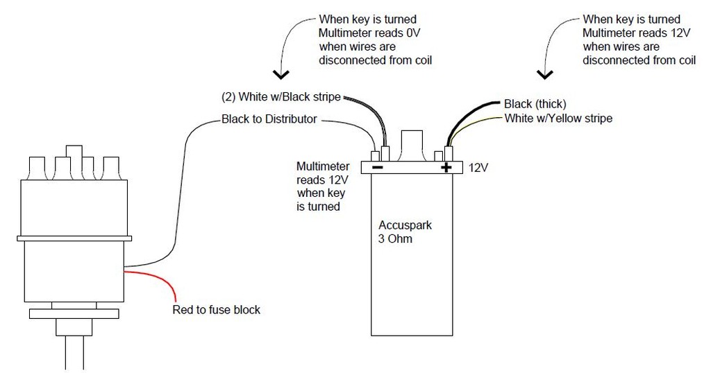
This is where it gets weird. The coil shows just under 12V on the negative terminal, when the key is turned. That seems wrong to me. Because if there’s power coming from the negative of the coil, putting the negative from the coil to the distributor isn’t going to work.
Did I burn something. Coil? Distributor?
See below.
Jamie
https://www.howacarworks.com/basics/how-the-ignition-system-works
and
https://auto.howstuffworks.com/ignition-system.htm
(There are 6 pages to the link above).
Suffice it to say that I do not think you damaged anything. It is not a surprise that you are measuring 12V between coil (-) and ground with the ignition on. If the module is NOT conducting (the equivalent of points are open), then you WILL measure 12V on coil (-). When the ignition module is conducting (equivalent to points closed) then you will find something close to zero volts on coil (-). Your measurement of 12V on coil (-) merely suggests that your electronic ignition module is "off", not conducting, open.
Module not conducting (points open): 12V from the fuse box, to coil (+), through the coil, onward to coil (-). There is no path to ground at this time so you WILL see 12V on coil (-). Since there is no path to ground at this stage, the coil just acts like an extension of the white wire... you will find 12V on its end... coil (-).
Module conducting (points closed): 12V from the fuse box, to coil (+), through the coil, onward to coil (-), through the module/points, to ground. Zero volts on coil (-). With the points closed there is now a path to ground. Coil (-) is now going to read Zero volts.
The points (or your electronic module) serve as a switch for current flowing through the coil. Every time the points close (module starts conducting) current flows through the coil developing a magnetic field in the coil. When the points open (module not conducting) the flow of current is stopped, the coil's magnetic field collapses, and a huge voltage pulse is created on the high-tension (spark plug) side of the coil. To create the spark it is necessary for the module or points to keep switching on and off which is handled by the rotation of the shaft in the distributor.
Again, read over the links above. If you want more information on ignition systems you can visit the link below and look for my document on Lucas Points Ignitions.
https://sites.google.com/site/purlawson/home/files
Yes, the article is about points. However, your electronic ignition module is just a set of electronic points.
|
|
Total posts: 82
Last post: Jul 27, 2019 Member since:Jun 24, 2014
|
Cars in Garage: 0
Photos: 0 WorkBench Posts: 0 |
Thanks for your patience on this. Unfortunately it’s just not working. Let me break things down to the simplest form (for me).
Please correct me if I’m wrong on anything below.
1) The coil needs 12V power
2) The coil needs to be grounded
3) The distributor needs 12V power
4) The distributor needs to be grounded
5) The coil can get power from any switched power source
6) The distributor can get power from the coil
All seems logical, right?
This is where it gets weird. The coil shows just under 12V on the negative terminal, when the key is turned. That seems wrong to me. Because if there’s power coming from the negative of the coil, putting the negative from the coil to the distributor isn’t going to work.
Did I burn something. Coil? Distributor?
Jamie
|
|
Total posts: 9241
Last post: Aug 17, 2023 Member since:Jun 5, 2000
|
Cars in Garage: 0
Photos: 0 WorkBench Posts: 0 |
|
From previous posts:
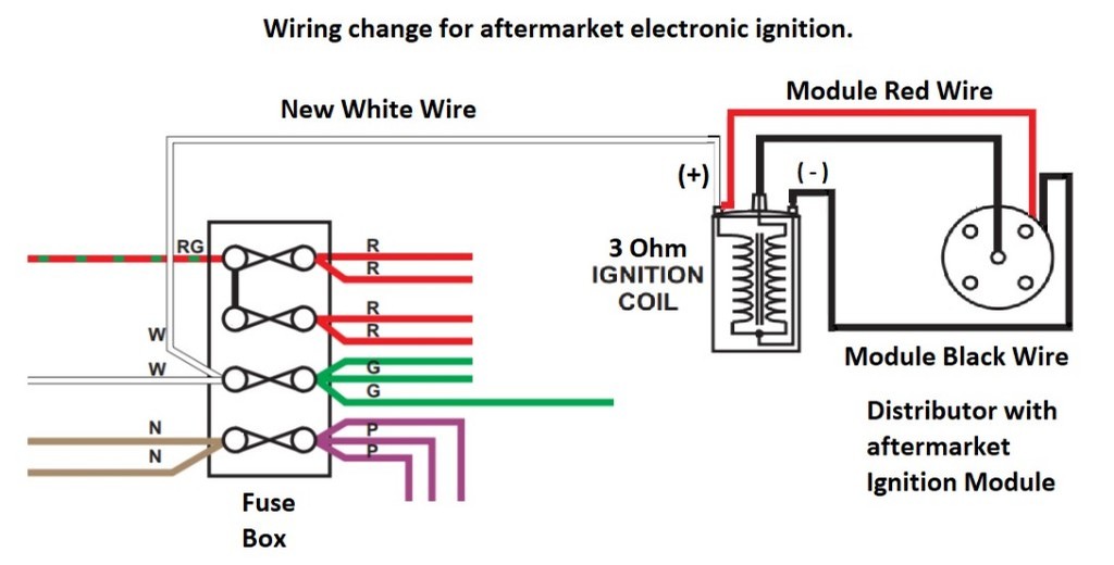
The distributor's red wire is used to power the electronics inside the ignition module. It needs a full +12V and should not be powered through a ballast resistor or resistor wire. If you use the existing black (white/pink covered with shrink tape) wire to supply your 3 Ohm coil, the spark will be WEAK because the coil will not get full voltage. ver
Do this.
Distributor RED wire to coil (+)
Distributor BLACK wire to coil (-)
Remove the BLACK (white/pink covered with shrink tape) wire from coil (+) and tape over its female terminal so it won't touch anything.
Go to the parts store and buy a small package of WHITE 16 AWG hookup wire. Also buy a crimp terminal assortment and a set of crimping pliers if you don't already have them.
Run a new white wire from coil (+) to the fuse box. Connect the fuse box end of the new white wire to any fuse box position that already has white wires on it.
Do not connect the white/black wires to the coil at this time.
What does this do?
The new white wire will supply the (+) terminal of your new 3 Ohm coil with full voltage.
Since the distributor's red wire is also on coil (+), the ignition module under the dizzy cap will get full voltage.
The black wire going from the distributor to coil (-) provides the normal path to ground for the ignition system.
I asked that you leave any white/black wires disconnected for now. You may find one, or three female terminals on white/black wires. With them disconnected any factory tachometer will not work. Once you have spark and a working ignition system we can discuss the white/black wires more.
|
|
Total posts: 82
Last post: Jul 27, 2019 Member since:Jun 24, 2014
|
Cars in Garage: 0
Photos: 0 WorkBench Posts: 0 |
 First of all, thanks Doug for that great response. Unfortunately I'm no electrical engineer and I just can't seem to figure this out.
I plan on using the new 59D distributor and the Accuspark 3 Ohm coil that came with the new engine.
You mentioned a white/pink wire, but I don't have one of those, so I'm not sure what was meant by that. Someone let me know if that's something that I need to be concerned with.
The last two paragraphs are confusing me and seem to contradict. You say that supplying a ballast coil with 12V, will cause it to overheat. Then you say that if I want to use the 59D and retain the ballast ignition that I'd need to add a second 12V supply. Wouldn't supplying it with 24V be worse and make it overheat faster?
Did you actually mean if I want to use the 59D and use the standard coil, I'd have to add a second 12V supply?
I've drawn a diagram of how I have things currently (no pun intended) hooked up.
Jamie
|
|
Total posts: 14000
Last post: Jun 29, 2025 Member since:Jan 22, 2003
|
Cars in Garage: 4
Photos: 381 WorkBench Posts: 1 |
|
I can't add to the great info given here on your topic...... I'm lousy at diagnosing ignition issues
"Everybody should own a MINI at some point, or you are incomplete as a human being" - James May
"WET COOPER", Partsguy1 (Terry Snell of Penticton BC ) - Could you send the money for the unpaid parts and court fees.
Ordered so by a Judge
|
|
Total posts: 9241
Last post: Aug 17, 2023 Member since:Jun 5, 2000
|
Cars in Garage: 0
Photos: 0 WorkBench Posts: 0 |
|
You have just mentioned the presence of a white/yellow wire. That confirms that regardless of what you want to do now, your car was built with a ballast ignition system. Remember that in an earlier post I asked you to measure the resistance of the two coils you have. That is now very important. You have to choose whether you want the car to retain the ballast ignition or convert back to a standard ignition. That will determine what coil is required. That will also determine which (if any) wiring changes will be required.
Regarding the 998 and 1275 distributors, don't focus on the displacement, for now focus on the dizzy drive type and block type. There are two main distributor types A-series and A+. The two types have very different drive dogs on the bottom of the distributor shaft. ANY A-series distributor can be placed in ANY A-series block. The same applies to the A+ blocks and their distributors. What will be different between a 998 and 1275 distributor will be the advance curves. That means IF your 998 and 1275 distributors are the same type you can place either in the block. However, neither may have the correct advance curve for your engine build. Those "universal" new distributors (like your 59D) may fit everything out there but their advance curve is probably not specifically matched to your (or anyone else's) engine. If the old 998 dizzy has points and fits the block... install it for now. All that will be wrong is the advance curve. You won't have an optimized dizzy but for now all you want to do is get the engine running and go through your 20 minute fast idle break in.
The following comments are my personal opinions and provided only as suggestions regarding which ignition system path to follow.
What is a ballast ignition system? It is a method of providing the coil with higher voltage during cranking so the spark is hotter, therefore making the engine easier to start. It is typically NOT needed with electronic ignitions. It was not used on earlier points ignitions. It was used in the early to mid-1970s on MANY makes and models of cars. It was a design improvement developed towards the end of factory points ignition systems. The Lucas white/pink resistor wire has a terrible reputation of a way to implement the ballast resistor in ballast ignition systems.
If you want to use your new 59D distributor, there is no reason to retain the ballast ignition system. It is very easy to bypass the white/pink wire. You can leave the white/yellow wire or remove it. Most importantly, if you choose to do away with the ballast ignition system you MUST change the coil to one measuring about 3 Ohms on its low-tension windings.
If your coil measures 1-2 Ohms, it is a BALLAST ignition coil. If your coil measures 3-4 Ohms, it is a STANDARD ignition coil. If you supply a ballast coil with 12V, it will overheat and a lot of the other ignition components will fail prematurely. If you fit a standard coil to a ballast ignition system, it receives about 1/2 to 2/3 the voltage it needs. That results in very weak sparks or no sparks. Again, you must choose which ignition system you want and select the right coil for it.
If you choose to use your new 59D distributor AND retain the ballast ignition, you MUST run a new switched +12V white wire to the red wire of the PowerMax ignition module so that the module's electronic parts receive enough voltage to work properly.
|
|
Total posts: 82
Last post: Jul 27, 2019 Member since:Jun 24, 2014
|
Cars in Garage: 0
Photos: 0 WorkBench Posts: 0 |
Thank you for the incredible information! I will read all 7 pages thoroughly. However, I did get impatient and put the car away for the winter. Even though I've lived in Wisconsin my whole life, I still hate having to scrape my windows. I do have access to the engine compartment and passenger side door, so I could try to get it running. Unfortunately the recommended break-in is 20 minutes at 2000 rpms, which wouldn't be good to do in an attached garage. If there's a nice weekend and I can get a spark, maybe I'll pull it out and take it off the dollies.
I'm not sure that the old distributor will work because the previous engine was a 998 and the new one is a 1293.
I do have two white with black stripe wires paired together that were connected to the negative terminal of the coil. The other pair is a white with yellow stripe and a white with pink. Unfortunately when I cleaned out the garage, I've misplaced by wiring diagram. Luckily Sean provided one, but the one I had was in color (much easier to read).
I'm busy with life at the moment and will let you know how it goes.. or more likely, if I have questions.
Thanks much!
Jamie
P.S. I have a bunch of 998 parts, including the block, which includes crank, pistons, etc... If anyone is interested, message me.
|
|
Total posts: 9241
Last post: Aug 17, 2023 Member since:Jun 5, 2000
|
Cars in Garage: 0
Photos: 0 WorkBench Posts: 0 |
|
However, electronic ignitions need full 12V on the red wire. Jamie said the black wire on coil (+) was actually spliced to a white/pink wire. When coil (+) is fed by the white/pink wire (a resistance wire) the ignition module cannot have its red wire connected to the coil. The ignition's red wire must be connected to a switched +12V supply.
Cars with points distributors and a tachometer will have (2) white/black wires. One short wire goes from the coil to the distributor. The second goes from coil (-) to the tachometer. On cars with electronic ignitions, the short white/black between the coil and distributor has no purpose and can be left disconnected at both ends. If your car has a tachometer, the second white/black wire is left on coil (-). During troubleshooting, disconnect the tachometer's white/black wire when it is fitted.
Jamie, your last post suggested that the distributor is new to you and has not been used before. If that is true, take it back out, put in the old distributor, and get the engine running on it first. Once you have the engine running on the old distributor you can move forward with the new electronic ignition.
In a previous post you asked if you could just hook up the wires to coil positive and get a spark at a plug resting on the cylinder head. The answer is "not really". Rather than go into depth here, please visit the website linked below where I store some of my files. Download a copy of "Lucas Points Ignitions" and read over the first sections on how the system works.
https://sites.google.com/site/purlawson/home/files
Succinctly, you have to have power to coil (+) and a ground connection from coil (-) THRU the distributor. As the points open and close (or module switches on and off) the coil has current flowing through it which then stops. When the flowing current stops (points open) you get a spark. Therefore, you have to have power and ground connections and a functional switch (points or ignition module) to get a spark.
Please clarify if this engine has ever run with this new distributor.
|
|
Total posts: 1456
Last post: Jan 31, 2022 Member since:Sep 8, 2003
|
Cars in Garage: 1
Photos: 186 WorkBench Posts: 0 |
|
Looks like you have some extra wiring there...
The pair of white/black wires being attached to the coil sounds wrong, you may have both ends of the same wire attached to the coil.
White with black tracer should go from from coil to dizzy
Switched power (white) should go to coil positive.
The black and red wires could likely be removed unless perhaps there is a tach in the car, I would remove them while troubleshooting though.
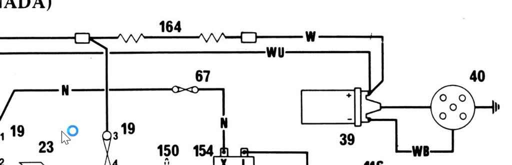
Here is the Canadian wiring diagram
https://www.minimania.com/images/wiring/PDFs/wiring10.pdf
EDIT, I looked at the photo on a bigger screen, are you running points or a pertronix ignition in the dizzy?
Sean Windrum
1996 MGF VVC
1970 1275 GT Racer
66 Austin Countryman
63 997 Cooper (Under Construction)
63 MG 1100
|
|
Total posts: 9241
Last post: Aug 17, 2023 Member since:Jun 5, 2000
|
Cars in Garage: 0
Photos: 0 WorkBench Posts: 0 |
|
How are you checking for spark? I suggest you place a spark plug wire in the high-tension terminal of the coil. Put a spark plug in the other end of the wire and rest the plug on a bare metal spot on the engine. While turning the engine over on the starter watch the spark plug and note if you see sparks across the plug gap.
A test light is a very simple device used to look for electricity. You can buy or make them. Google for "test light" and you'll see a lot of pictures of the purchased type. If you want to make your own, get something like a turn signal bulb. Solder two wires to it, one on the lead bump on the bottom, and one on the metal socket at the base of the bulb. You use the test lamp between ground and a circuit/wire where you want to find power.
There is a problem with your distributor wiring. However, if the dizzy was working before, it should be working now. The problem is that black wire on coil (+) which is in turn spliced to a white/pink wire. That white/pink wire is a ballast resistor element. It is used to drop the voltage on the ballast type ignition coil. If you try to power the ignition module (red wire) with the white/pink wire the module does NOT get enough voltage.
You said you had two coils. With the low tension wires removed, use a multimeter to measure the resistance across the low-tension terminals (spade lugs) of each coil and post back with what you measure. We need to understand which coils you have available and then decide your best path forward.
|
|
Total posts: 82
Last post: Jul 27, 2019 Member since:Jun 24, 2014
|
Cars in Garage: 0
Photos: 0 WorkBench Posts: 0 |
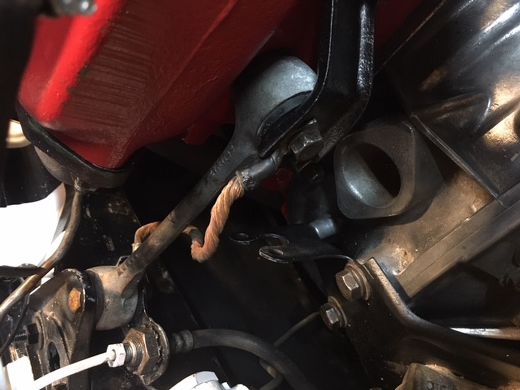
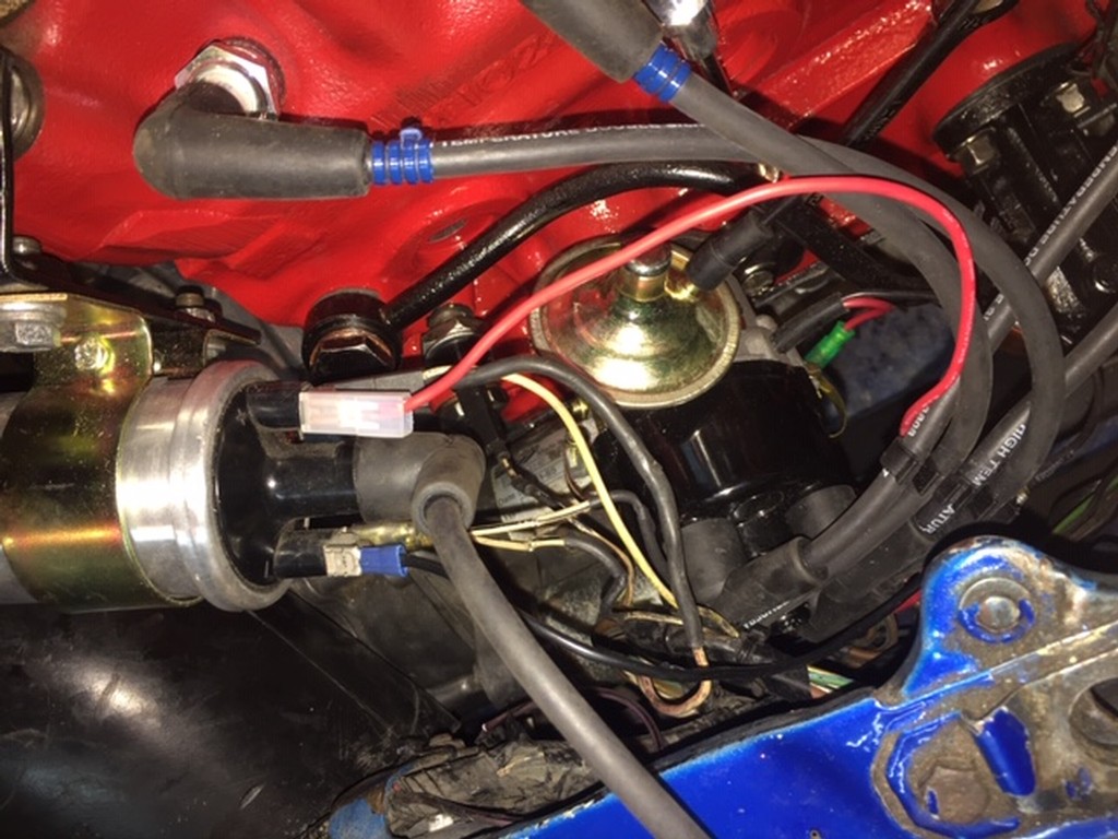
The first picture shows the ground wire. I have it going from the engine to the frame with the engine mount.
The second picture shows the wires that I have plugged into the coil.
After looking at things more the thicker black wire, just has some shrink tape on it. It's actually while with a pink stripe.
The dizzy cap shouldn't matter at this point, I'm trying to get spark from the coil itself. So the distributor isn't even in the picture just yet.
I'm not sure what a test lamp is. Could you explain?
The dizzy is brand new (as far as I know), the red and black wires were on it when I got it. If you look at a 54d distributor on this website you'll see they have these wires. Unfortunately I've misplaced any documentation that came in the package (if there was any) and there's nothing on this website that explains what these wires get attached to.
I should be able to hook the positive wire(s) to the coil and place a spark plug in the lead that normally goes to the dizzy, and touch the spark plug to a stud on the engine and get a spark when turning over the engine. Correct?
Jamie
|
|
Total posts: 9241
Last post: Aug 17, 2023 Member since:Jun 5, 2000
|
Cars in Garage: 0
Photos: 0 WorkBench Posts: 0 |
|
You said there is a black wire on coil (+). That is either a mistake or something added by a previous owner. Black wires are earth/ground connections and should not be on coil (+). Trace that black wire and let us know where it goes.
I suggest a few quick tests.
1) Look inside the dizzy cap and make sure the carbon button is still in the center and pushed out by its spring.
2) Connect a test lamp between coil (-) and ground. Have a friend crank the engine over while you look at the test lamp. Is it flashing, steady off or steady on?
3) Temporarily disconnect the white/black wires from coil (-) and try to start the engine.
The red and black wires you mention indicate that the dizzy has an aftermarket electronic ignition. Was it fitted recently?
|
|
Total posts: 82
Last post: Jul 27, 2019 Member since:Jun 24, 2014
|
Cars in Garage: 0
Photos: 0 WorkBench Posts: 0 |
Here’s an explanation of the wires I have connected to the coil. The red wire from the distributor is connected to the positive side. A pair of wires, one thick and black and the other thinner and white, which show over 12 volts on my multimeter, are on the other positive side connection.
Here’s what I have on the negative side of the coil. The black wire from the distributor and a pair of white wires with black stripes. These wires show no voltage on my multimeter.
My ground is on either side of the engine mount on the left side of the engine. I also hooked up a jumper cable to provide another ground, just in case.
Am I missing something? Would any pictures help?


