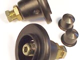
Elsewhere on in Calver's Corner I have covered lowering the Mini by modifying the standard existing components, and the essential problems to look out for. However, most folk don't want the aggravation of messing about cutting cones and the possibility of repeating the process should the result not be what they want. The easiest solution is to fit an adjustable cone - to all intents and purposes an adjustable spring platform.
Front end:
To enable this to be done, you will need the special tool manufactured for compressing the rubber springs. Without this you will not get the ally trumpets out since the rubber spring is applying considerable pre-load force on the cone and knuckle assembly. They are readily available from Mini Mania and are not expensive. Every long-term Mini owner should have one anyway! It is possible in certain areas to rent one if buying one is out of the question. Perhaps a local Mini owner or club would be willing to share theirs.
1. Slacken off the wheel nuts, jack the car up, and lower onto axle stands positioned underneath the front subframe. I usually site them directly under the inner bottom-arm pin. Make sure the car is secure and stable then remove the wheels.
2. Remove the bonnet (hood). On post 1976 (rubber mounted front subframe cars) remove the 1-5/16"AF-headed bulkhead to subframe tower bolt (early cars use two smaller bolts). I strongly advise doing one side at a time, although hopefully the car won't go anywhere if securely positioned on the axle stands!
3. Use the spring compressor as described in the literature supplied with it. If none is available - the Mini Mania-sourced type is a two-piece tool - a threaded rod with large cast T-handle screwed onto the top and a T-bar at the very end, and a long metal tube with a plate at one end. The metal tube is placed with the plate against the bulkhead. The 'pointy end' of the threaded rod placed down inside this, and screwed into the spring. The T-handle is then screwed down to compress the rubber spring. CAUTION; there are two types of threads used in the rubber springs. Pre 1976 had a fine, 1/2"UNF imperial thread and post 1976 ones had a coarser, 14mm metric thread. Don't wind one into the other - cross-threading the rubber spring will be a nightmare of epic proportions! Smear a blob of grease onto the thread on the rod, and take your time to carefully screw the rod into the spring. If you are getting a great deal of resistance - you may be using the wrong thread type. Once happy you've got the right thread match, wind the rod in at least nine or ten full turns to ensure complete thread engagement in the springs threaded section. Use the cast handle to compress the spring. This will take some doing as the force that spring is applying is in the thousands of pounds area. Compress it about 1/2".
4. Remove the bump-stop fixed to the subframe tower elbow to give maximum working room - two nuts on inner side of tower for early non-rubber mounted subframes, one nut for rubber mounted types.
5. Position the jack underneath the bottom swivel pin on the outer end of the bottom arm and jack the suspension up until the ally cone is just re-engaging the rubber spring. Now remove the rebound buffer under the top arm, fixed to the subframe by a Pozi-drive screw. You may need an impact driver since these can get corroded in. Doing this will maximise the 'droop' available on the top arm - again for maximum working room.
6. Undo the top and bottom damper fixings and remove the damper.
7. Lower the jack and allow the suspension to go to full droop.
8. Compress the spring just far enough so clearance is given to remove the cone. Fitting the Hi-Lo back in will be easier because it can be made shorter.
9. Getting the old nylon cup out of its socket can be trying - the easiest method I have found is to use a butane gas torch to melt the thing. Alternatively a very sharp craft knife (Stanley knife) can be used to cut it to pieces. Both are far easier than trying to pull it out with grips of some sort. Since Hi-Los (and some of the other derivatives) come with new knuckle cups, destroying them isn't a worry. I would strongly advise, however, fitting complete new knuckle assemblies since they are so cheap. Clean any corrosion out of the nylon cup socket in the top arm, and grease lightly to abate further corrosion.
10. With the lock-nut screwed down to the knuckle seat end, screw the adjuster as far in to the cone as it will go, then screw it out again counting and making note of the number of turns it takes to set the platform to the original cone height using the one removed as a gauge. Remember - it's the distance from the spring platform lip to the end where the knuckle fits that's important - so don't just sit the Hi-Lo down on a bench - the adjuster may hold it up, and the raised seat locating ridge may be different to the standard one. Now screw the adjuster all the way in again.
11. Use copper anti-seize grease on the knuckle pin to adjuster bolt joint, plenty on the entire thread length of the adjuster bolt and around the spring seat to avoid corrosion seizure then re-assemble the whole lot in reverse order of removal, substituting the Hi-Lo adjustable platform for the standard aluminium cone. Unscrew the adjuster by the relevant amount of turns noted to return the adjustable platform to the 'as standard' position - this will give you a near-standard ride height to work from - then do the other side.
12. Refit the wheels, and lower the front onto the ground
Rear end:
1. Slacken the wheel nuts, jack the car up and set it down onto axle stands, ensuring the car is stable then remove the wheels.
2. Position the jack underneath the drake drum on one side, and take the weight off the radius arm.
3. You need to disconnect the top damper fixing. I always find this a great deal easier if the boot (trunk) lid is removed first. Saves having to try and work at full stretch and awkward angles. Particularly as the fuel tank needs swinging in to the boot space to afford access to the left hand damper fixing. A little forethought here will see a bare minimum amount of fuel in the tank whilst this operation is being carried out to avoid the risk of spillage. To remove the tank, release the holding straps and filler cap. Ease the tank inwards to pull the filler neck back through the large body grommet. Once the filler neck is clear - re-fit the filler cap, and swing it into the boot space far enough to allow access to the top damper fixing.
4. Lower the jack and allow the radius arm to hang at full droop/rest on the floor. Slacken the lower damper to radius arm fixing, compress the damper and swing it back towards the rear of the car to maximise access to the rear suspension. If the dampers are to be changed, remove the lower fixing then the damper.
5. No spring compressor is needed at the rear, as there is sufficient droop available to allow the cone and spring to be removed. The rear suspension is under less spring pressure so requires no pre-load to be used. However, if the assembly has been in situ for some time, the spring may be stuck to the cone by corrosion. This will mean some use of a hammer and possibly large chisel/pry bar to get them apart. Soaking the joint in WD40 pays dividends.
6. Once out, repeat the knuckle cup removal and socket attention as detailed in the front suspension operation.
7. The rear Hi-Lo uses a long rod to connect the knuckle to the adjuster - substituting the length of the long rear cone. Repeat the method outlined in the front section for setting the over-all 'standard' cone length, including anti-seize greasing.
8. Reassemble in reverse order of fitment. If a change of dampers is decided on, and removal of the existing ones leaves the eye-bush inner metal sleeve stuck on the damper mounting pins (front and/or rear), use that butane torch to heat the sleeves up a bit and remove with Vise/Mole grips. Clean the pins up with abrasive tape and smear anti-seize grease all over them before fitting the new units. Do not be at all surprised if the car still looks too high once you've set it back on the ground. You have disturbed the well-settled suspension components, and the slight increase in the spring platform seat will cause the spring to run in a slightly different 'position' - raising the ride height slightly. Drive the car around for about a week to settle it all down. This is why I described setting the Hi-Los to the standard-ish length initially. You don't want tyres whacking bodywork or suspension going bound before you've had time to thoroughly investigate what is going on as the car is lowered/raised. When adjusting the ride height do not adjust one corner only. I start out by lowering the car as far as it will go without disengaging the cones from the springs (particularly at the rear) even amounts - count the number of turns - either side front and rear. Then start winding the adjusters to raise the car to the required height at each end. For full explanation on setting ride height see 'Suspension - basic set-up method' For the record the front trumpet height as standard is 3.750" and the rear is 12.375" on the latest post 1979 cars and all vans/estates. The earlier ones were around 12.125". This is from the knuckle end to the spring platform face, both measured from where the spring butts up against it, NOT the over-all height.
Useful part numbers:
HMP141303 Pair of adjustable spring platforms/cones with new knuckle cups. Same items for front or rear.
C-STR644 Complete set of adjustable struts, front and rear.
HILO-01 Pair struts for HILO when used on rear.
HILO-02 Short hex adjuster key for front if required.
HILO-03 Long hex adjuster key for rear if required.
660330 Spring compressor, has both pieces for imperial and metric threads.
GSV1118 Knuckle/cup assembly, pre 1990.
GSV1188 Knuckle/cup assembly, post 1990 with built-in spacer to raise suspension for clearance on 12" wheels.
21A423 Knuckle nylon cup.
21A425 Knuckle gaiter
Tool10 Simple caster/camber gauge.
Tool11 Simple tracking gauge.
2A4332 Early 2-stud fixing front bump-stop.
FAM2764 Later single fixing front bump stop.
2A4267 Rebound buffer.