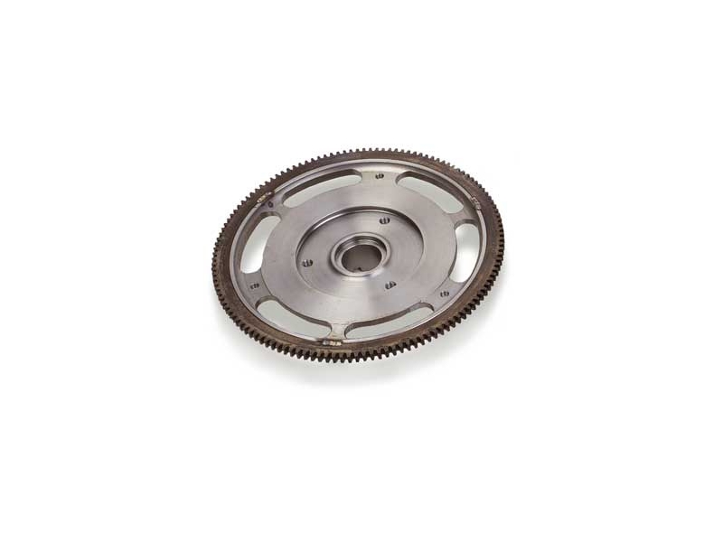

The latest refinement of the Ultra-light Mini flywheel is now made symmetrically to reduce harmonics vibrations caused by earlier versions - yet it still weighs just over 8 lbs.! This is considerably lighter than a safely lightened standard iron flywheel, and also provides a much hardier clutch surface..
Effects of lightening rotating engine components: (0.5 x n2 x r2 + R2) / R2 n = total gear ratio (gear ratio x diff ratio) r = radius of gyration R = Radius of wheel/tyre This formula gives what accelerative weight the engine sees of the car per lb. Radius of gyration of a transverse engine's flywheel is approx. 3.75" So to determine "weight loss" for a flywheel weight of say 18 lb to 10 lb, the engine would see an overall weight loss of the car to accelerate in first gear of: 3.33 = 1st gear of 4 synchro 'S' box 3.44 = diff ratio (0.5 x (3.33 x 3.34)2 x 3.752 + 9.52) / 9.52 = (0.5 x 131.2 x 14.06 + 90.25) / 90.25 = 1012.59 / 90.25 = 11.22 lbs So for every 1 lb removed from the flywheel, the engine sees 11.22 lbs less to accelerate off of the total car. Therefore by lightening the flywheel by 8 lb, the engine sees a total reduction of the cars accelerative weight of 89.68 lb.
A set of three spacers are supplied with the flywheel used to maintain the correct postion of the straps. They are .425" thick, .620"OD and .380" ID
Fitting Instructions for Part# C-AEG619 - Ultra Light Competition Flywheel, 8.5lb
* This flywheel is not balanced so should be before use, along with the prospective clutch assembly.
Before fitting the C-AEG619 ultra-light steel flywheel, carefully examine the crankshaft taper for any burrs or other protrusions caused by fret-welding of previous flywheels. All protrusions of any sort must be removed as they will cause incorrect seating of the flywheel which could, in turn, cause this fret-welding to occur and permanently damage both crankshaft and flywheel.
A recognized method of ensuring correct fit is to use fine valve lapping paste to lap the flywheel on to the taper. A good, correct fit will be confirmed by seeing an even grey finish over the whole of the taper on both components. The paste should then be thoroughly washed off using a strong cleaning solvent (such as cellulose thinners or brake cleaner).
As the flywheel is of a much thinner section than the standard one, distance pieces (spacers) are provided to re-align the clutch drive straps. However it is very strongly advised the following method is used to establish correct alignment:
If the pressure plate clutch plate friction face needs re-surfacing, get it machined to clean it up. Make sure the engineering company doing the job records the amount taken off as once done, the recorded amount needs removing from the tops of the 'horns' that stick up to ensure proper clamping force is achieved. If this is not done, clutch slip is inevitable. If using a pressure plate of unknown history, it is IMPERATIVE the clutch drive straps are set at the correct height. Many get this wrong and end up with a slipping clutch for some seemingly unfathomable reason. The following should also be carried out if the flywheel has been machined, or of unknown history also:
- Place the pressure plate 'horns' upper-most on something to hold it off of the work surface but not interfere with clutch plate of flywheel
- Place the clutch plate in position, with the protruding primary gear spline boss on the underside facing the work surface
- Place the flywheel in position
- If the drive straps are holding the flywheel up, or are under tension pressing on the pressure plate 'horns', more spacer-washers/shims are needed between the drive straps and flywheel
- If there's a gap between the drive straps and pressure plate horns, the spacing between the straps and flywheel needs reducing
- If no drive straps are fitted, using a straight edge or drive strap fitted to one of the horns, measure the existing gap between flywheel surface and underside of straight edge/strap, and make suitable spacers to this measurement
- Where extra drive straps are fitted, as in racing (3 on each location instead of the original two), it is essential to machine the thickness of the drive strap off of each pressure plate 'horn' and spacer to re-gain correct diaphragm clamping action to avoid clutch slip
The idea is to set the straps so that when they are in their 'as assembled' position, they are not under tension, nor are well clear of the pressure plate horns. They should be JUST touching. Under tension the clutch will slip due to decreased clamping pressure. Too far clear may cause disengagement problems.
-
Price : $6.90
-
Price : $9.90
-
Price : $5.90
Loading...
Loading...
Loading...
Loading...
Loading...


