Converting from Wet to Dry Suspension in your Classic Mini Cooper
The steady decline over the past several years of readily available hydrolastic displacer units has prompted an escalation in the number of folk asking how to go about swopping from hydrolastic (‘wet’) suspension systems to the far more wide spread ‘dry’ set-up. As in all things, with enough skill, enterprise, facilities, and money - anything is possible. Being all too ready to oblige in anyway I can, here’s the relevant details of the most practical way of going about it for the majority. It's not the 'be-all-and-end-all' definitive article on all the possible permutations, just the simplest way out. And it’s nowhere near as difficult as most folk seem to think it is.
Paddling about in the past
Introduced to production Minis in 1964, the system had actually been under development by the wizard Issigonis and gifted engineer Alex Moulton for some years before hand. In fact Issigonis had wanted this fitted to the Mini right from the word go. The powers that be denied him this on the grounds of cost and the fact that they hadn't managed to cure persistent production problems culminating in a high percentage of the items produced being faulty/failing in use and therefore rejected/scrapped.
Alex Moulton came to the rescue by coming up with the design for the rubber springs in a big hurry to 'fill in' for the missing hydro units on the early production cars, then ended up being used on the vast majority of Minis! The man being the man however, Issigonis bludgeoned the hierarchy until he finally got his way. His primary reasons for applying the hydro system to the Mini (at further/considerable expense - much to the hierarchy’s chagrin) was to eliminate the choppy ride given by the rubber springs and pitch under acceleration/braking. Searching for the ever elusive ‘Rolls Royce’ ride quality.
Unfortunately the pitching problem worsened, particularly under severe use of the go/stop pedals. Fully laden, rear end sag caused complaints by low flying aircraft - German authorities taking the severest line by banning hydro cars from sale in Germany. Further development/refinement was needed, but the hierarchy cried ‘enough’, and withdrew fitment in 1969 - although it stayed fitted to the S right up until it’s demise in 1971.
In fact a few early GTs were hydro equipped too. The BMC big-wigs decided the extra expense of manufacturing the complex displacer units, and further development funds needed just weren’t justified for the perceived little extra gained. Shame, because many years further on, some individual development has seen superior results over the dry set up. So much so that there’s discussions about making new displacer units using modern technology!
Main frame
Without a doubt, the easiest way to do the conversion is using the complete under-pinnings from a dry suspended Mini that’s had it’s usefulness terminated - MOT failure, excessively dissolved bodywork, maybe crash damaged/insurance write off. Anything’ll do. Van, estate, saloon. Preferably the pre rubber mounted type - details ‘why’ below. New front subframes are a fortune, so obtain ‘used’ unless excessively rich! Make sure you carry out a careful inspection to make sure it’s in good nick. Particularly around the tie rod mounting lugs and rear ‘legs’. Especially if it’s from a crash damaged car. Measure the thing up for 'square' too.
Starting at the sharp end, whichever way you go engine removal will make things a whole lot easier. I know some folk advocate removing the entire engine/subframe/suspension assembly in one go by lifting the body over the top of it all - having disconnected everything first, naturally. I did this once, never again. You need an army of companions to man handle everything about. A right pain.
Now, it’s entirely possible to modify the hydro front subframe to accept the rubber springs and other necessary bits and pieces. The displacer unit is seated in the tower in the same way as the cone, the difference being the locating ring's size/shape. The displacer sits inside it’s seating ring, the cone outside. The diameters of these differ too, the hydro being bigger, and has lugs pressed into it. To get the rubber spring to fit the hydro ‘frame, these lugs need to be bent outwards. The rubber spring then locates inside the ring.
Sounds easy, eh? Achieving this is accompanied by all kinds of 'blue' air and skinned knuckles. More often than not, eventual submission and fitment of a dry ‘frame!! It’s all down to access - or lack of it (as in ‘severe’). There are ways round it, but we’re supposed to be doing this the easy way, remember? Then you need to drill holes in the tower outer ‘elbows’ to take bump stops. Use the later single stud fixing as this eases the whole drilling/fitting thing.
So it’s a dry subframe then. The easiest is to use the pre 1976, non-rubber mounted type, as this bolts straight in using the fixings from the donor car except it uses bolts in the towers rather than the studs of the hydro one. Floor pan and front panel mounting holes are all in the same places. Using the later rubber mounted one has complications. Leyland decided to rubber-mount the front subframes in an effort to make the aged Mini more civilized.
Consequently they isolated the front ‘frame from the shell using rubber mounts between the front, rear, and tower mounting points. These make it easily identifiable, along with the humungous, 1-5/16”AF-headed bolts used to fix the ‘frame to the shell through the bulk head into the towers. You’d need all these from the donor car - unfortunately ninety nine times out of a hundred they’ll all be shot so new ones would have to be bought - more expense! You need them bolts too - they’re real expensive new!! Make sure you get the metal washers under the bolt heads also. Although the lower front and rear mounting point holes are the same, the tower mounts present the biggest problem.
The post 1976 shells have a stiffening tube welded into the bulkhead to prevent it from being deformed/crushed by the bolt. This doesn’t happen when doing the big bolt up. When using the standard rubber tower/bolt mounts, the design has the bolt bottoming out on its thread to ensure ‘space’ for the rubber mounts to work in. The deformation occurs in use, as the support tubes for the original twin bolt/stud fittings aren’t in the right places to be effective. Using solid mounts actually slightly improves things a bit - although causing slight deformation when doing the bolts up, the reduction in movement in operation reduces further deformation markedly. See separate article for bush and mounting options.
When removing the ‘frame assembly from the donor, make sure you unbolt and keep the top damper mounting brackets. They’re held to the body by four 7/16”-AF bolts wound into captive threads. These captive threads are on every shell, including the hydro cars - you may have to dig through the cack and poop to find them though!
Bringing up the rear
Again, as with the front, the hydro rear ‘frame can be modded to take the rubber springs. Same mods, but very, very much easier. However I don’t advise this unless the Min’s used solely for normal road use, carrying two people in the front, minimal luggage, and totally standard wheels/tyres and standard ride height only. Why? Coz that curious metal cone shape on the dry type acts as a variable spring platform - progressively increasing the spring rate as more load is applied. Carrying more load than the minimal amount mentioned above will have the tyres bashing the wheel arches. Trust me in this, that’s all the explanation you’re going to get, as it’s a bit complicated (not enough room here for full dissertation).
I’ve never taken a rear ‘frame out of a car and found it useable, so I don’t see why any of you should be any different! Useable, ‘as new’ condition, second-hand ones are rare. Considering the relatively low cost against the severe aggro of fitting a rear ‘frame - buy a new one. Treat it with some decent rust proofing gear, and have no worries. The fitting holes in the shell are all the same, so even the later post 1976 mounts will fit OK. Just remember when buying service parts (i.e. rubber mounts) which ones you’ve used.
Componentry
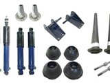
Pointy end first again. If you’ve persevered with mod-ing the hydro ‘frame (give that man a medal!) or have used just a dry ‘frame and mounts with no bits, it is possible to use all the hydro stuff plus the necessary additions - rubber springs, ally trumpets, dampers, top damper mounts and lower damper mounting pins. New knuckles would be a good idea too (those on the suspension, not your hand! Although…), as they are very cheap. Two of each needed of course!
The only flies in the ointment here are the top arms. Using the hydro items will give a stiffer ride as they’ve got a slightly lower working ratio (knuckle seat is a bit further out, nearer the swivel pin). Fine for a competition car, not so funny for a road car. Plus you need to drill the bump-stop mounting bolt hole out to 3/8” for the lower damper pin to fit.
And this is exceptionally difficult - buy a bucket load of drill bits, those arms are real hard! The top damper mounts bolt straight to the shell using the previously mentioned captive threads. The top pair are easily found since the metal block with the captive threads in is visible in the corners next to the tower mounting bolt heads. The other lower pair are hidden behind the inner wing near the subframe tower top - so it would be prudent to uncover these and clean/prepare the threads for use whilst the front 'frame is out of the car if that's the way you are doing the conversion. Bump stops need to be fitted to the subframe where you’ve drilled the necessary holes. I actually prefer the hydro bump stops, so drill the holes out in the mounting bracket to 3/8” and use cap head (Allen) bolts to mount the dampers. These go through the bump stop and the damper. Getting easier, isn't it?
Now the back end. As with the front you’ll need rubber springs, ally trumpets, dampers, suggest new knuckles for what they cost, new radius arm to wheel cylinder brake pipes (hydro’s are shorter as they fit under the arm instead of on top), and last but not least - hand brake cables. Two of each once more. Now, to avoid all sorts of hassle, it really is strongly advisable to use dry-type radius arms. The hydro design will see your Min fall flat on it’s arse unless you get some severely lengthened rear trumpets. Then there’s nowhere to bolt the dampers to. The dry type have a pin sticking out to take them, the hydro doesn’t. This damper mounting pin is part of the rear stub axle, swopping these can be an absolute nightmare and they’re not cheap either. It’s cheaper in the long run to buy a pair of completely refurbished dry arms. Honestly.
Other useful stuff.
Whilst you’re doing this, it’d be a good idea to give the entire suspension a good overhaul. The components needed to do this are very cheap, even if you go for up-rated stuff.
At the front, replace bottom arm bushes (slight snag, keep reading), tie-rod bushes, and check the top-arm shafts and bearings. These consist of two caged needle roller bearings, one pressed into each end of the top arm. They’re subject to seizure/wear as most folk completely neglect greasing them. Rebuild kits are reasonably priced. Once done, don’t forget to grease them regularly in future!! Bottom arm bush snag thingy - before buying parts for them, you need to check which type they are, The early arms used a top hat type bush, later ones a tapered, metal-sleeved type.
To identify, peer into the holes in the bottom arm. If the walls are tapered, use the later style bush. Parallel sides indicate the earlier type. Unfortunately you can only get up-rated bushes for the later tapered type. Using up-rated bushes improves stability - particularly the tie-rod ones. These reduce weaving under braking, and fractionally help to reduce roll (long story!). For material options, see separate article.
The radius arms at the rear are the biggest problem. If you use recon ones, no worries, but if you use the existing ones, overhaul the pins and bushes. Inexpensive to buy but a bit of a pain to fit since the outer bronze bush needs reaming after fitment. Most engineering companies can do this, but again - recon arms are really cheap when bought on exchange. Otherwise it’s just the ‘frame mounting rubbers that need attention.
Lastly, the only specialist tool you’ll need to do the job is the rubber spring compressor. Cheap enough to warrant the investment as you’ll need it again in the future.
Useful part numbers:
| Complete knuckle joint assembly - 4 per car | GSV1118 |
| Single stud mounting front bump stop - 2 needed | FAM2764 |
| Twin stud mounting front bump stop - 2 needed | 2A4332 |
| Front top arm rebound buffer - 2 needed | 2A4267 |
| Up-rated top-arm damper mounting pin (when up-rated dampers are fitted) - 2 needed | C-AJJ3361 |
| Standard Rover top-arm damper mounting pin - 2 needed | 2A4337 |
| Standard tie-rod bushes - 4 needed | 31G1155 |
| 'Top hat' type early bottom arm bush - 4 needed | 2A4294 |
| Metal-insert type later bottom arm bush - 4 needed | 21A1882 |
| Recon 'dry' rear radius arm - right hand | 21A392 |
| Recon 'dry' rear radius arm - left hand | 21A393 |
| Rear radius arm repair kit - 2 needed | GSV1125 |
| Radius arm stub axle with damper mounting pin - R/H | 2A7351 |
| Radius arm stub axle with damper mounting pin - L/H | 2A7364 |